
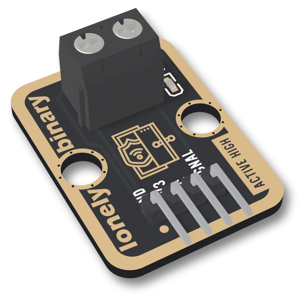
The TK107 at an angle: a black board with a gold border, lonely binary up the left edge, a tall black two-way screw terminal with two silver screws at the top and a small red LED and resistor beside it, a gold door drawing with a shield and wireless symbol, two round LEGO holes, ACTIVE HIGH up the right edge, and four right-angle pins labelled GND, 3V3, NC and SIGNAL.
VR

View it in VR

This board opens in a VR headset: life-size, or big enough to stand beside, with every pin and every part named where it sits. Open this address in the browser on a headset such as Apple Vision Pro or Meta Quest.

learn.lonelybinary.com/vr/tk107
You have this

Door Sensor

A TinkerBlock board that takes the two bare wires of a magnetic door or window sensor on a screw terminal and puts it between VCC and SIGNAL. A closed sensor reads HIGH; open, SIGNAL floats, because the board has no pull-down, so you set one in setup(). The red LED lights while the sensor is closed: it is not a power light.

Pull-down
Noneset INPUT_PULLDOWN in setup
Draws while open
0mA; about 0.3 mA closed at 3.3 V
VCC
3V3 or 5Vyour board's logic voltage
Wires
3of 4: GND, VCC, SIGNAL

Turn it over and see the three holes to wire: GND, VCC and SIGNAL. The screw terminal puts the sensor between VCC and SIGNAL; nothing on the board holds SIGNAL low when it opens, so your sketch sets a pull-down.

Product questions & answers ↓

Community

Product questions

See what other owners have asked, and read their solutions.

Ask a question ↗

Door Sensor

Loading discussions…

Need another
Door Sensor TK107
Order or missing parts?

Email us or reply to your order, and quote tk107 — that identifies the product. If something is missing from the bag, your order is the record of what shipped.

Take it with you

Point a phone camera at the code and this page opens there. It is the same address as the one printed on your box, so it is also what to show someone you are passing the board to.