What is in the box
Two things you will wire and four you will put in a drawer. The part worth memorising is the module's two headers, because they are in different orders and everybody wires one of them by counting across from the other.
What is in it
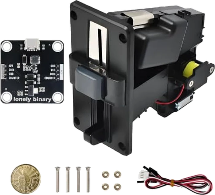
The acceptor and the module are the two things you wire. The screws and nuts are for bolting the acceptor into a panel — it is designed to be let into the front of a cabinet. The harness joins the acceptor to the module, and the token is for checking the mechanism turns over.
There is a printed quick-start guide in the box as well, and it is the same document as the one in the library's repository.
The module, pin by pin
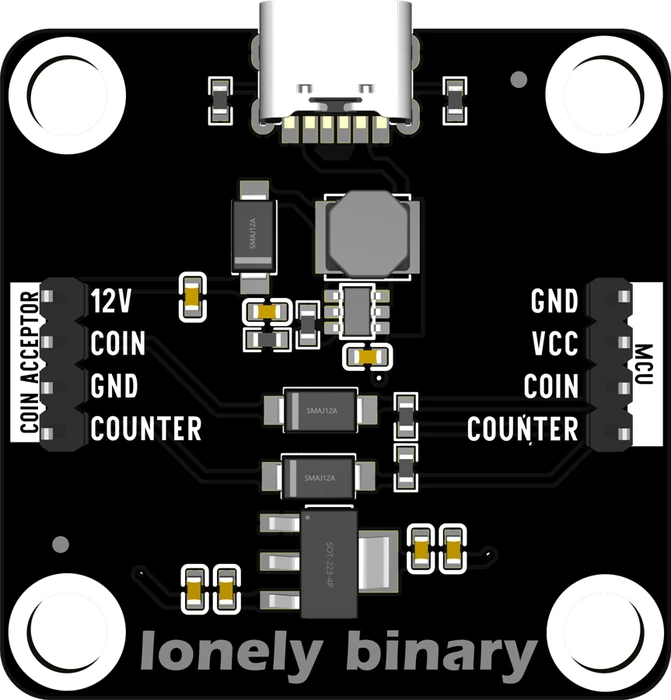
The board is a square with a USB-C socket on one edge and a four-pin header
down each side. The silkscreen names both: COIN ACCEPTOR on one, MCU on
the other.
The two rows are not mirror images of each other, and that is the single
most useful thing on this page. Count across the board from 12V and you land
on GND. Count across from GND and you land on COIN. Read the silkscreen
for each wire instead.
The acceptor
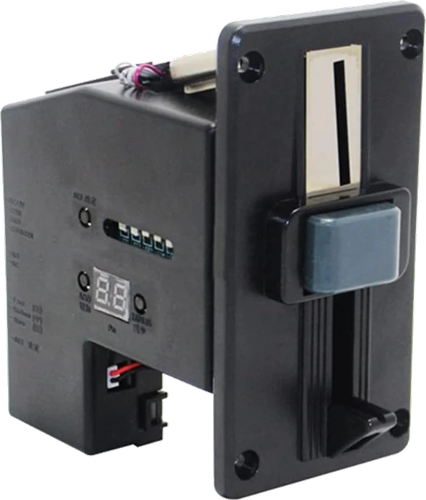
On the side there is a two-digit display, three buttons — +, − and SET —
and a row of small switches. The display and the buttons are how you tell it
which coins to accept; the switches set how it reports them. Both are covered
in the two switches and the two
pages after it.
Out of the box the acceptor knows no coins at all. It will reject everything, including the token, until it has been trained.
When it does not work
The module ships with headers fitted, in the photograph and in ours. If yours arrived with loose strips instead, solder them into the two four-pin rows — the silkscreen names every pin on the top side, so fit them from the top and solder underneath.
It is a token, for checking that the mechanism runs before you have trained it on anything. Do not train a coin type on it unless you actually want the machine to accept tokens — you would be spending one of your six coin types on it.
That is the trap. The acceptor-side header runs 12V, COIN, GND, COUNTER and the MCU-side header runs GND, VCC, COIN, COUNTER, so the pin directly opposite 12V is GND. Read the silkscreen for every wire rather than counting rows across the board.
Neither. There is no microcontroller in this box — the module has a power converter and protection on it, and the acceptor has its own fixed firmware you configure with its three buttons. Your own ESP32, UNO or Pico is the third thing, and you supply it.
Why the guide is so insistent about the adapter, and what a laptop port actually does.
One USB-C cable, and the 2 A rule →Edit this page — content/books/coin-acceptor/what-is-in-the-box.mdx
Questions about this product
See what other owners have asked, and read their solutions.
Arcade Coin Acceptor Module Kit, USB-C Powered
Loading discussions…
Discuss this article
Ask about this page. The answer stays here, on the page it belongs to, for whoever hits the same wall next.