Specifications
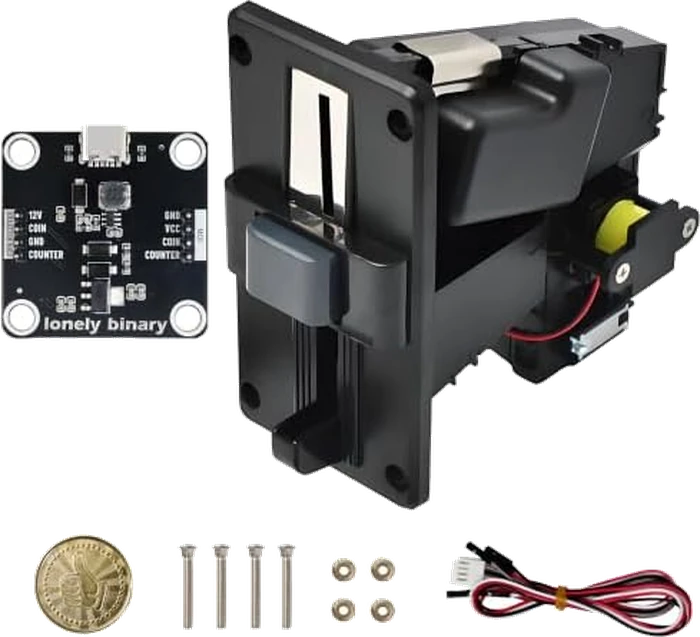
| In the box | The coin acceptor, the USB-C power and signal module, a wiring harness, four mounting screws with nuts, a test token and a printed quick-start guide |
|---|---|
| Module supply | USB-C, 5 V. A 2 A adapter or better — not a laptop port, which cannot hold the rail up when the coin motor runs |
| Acceptor supply | 12 V at 350 mA, made on the module by a boost converter from the USB-C 5 V. The 12V pin is an output, not an input |
| Signal output | 3.3 V as shipped, or 5 V with the selector on the back of the module. Active low: the line idles at the rail and each pulse pulls it down to ground |
| Signal pins | COIN, a burst of pulses whose count says which coin, and COUNTER, one pulse per accepted coin. Wire one of them, not both |
| Coin types | Up to 6, each one trained from 15 real coins and each given its own pulse value. No computer or software needed to set either |
| Pulse width | Set on the acceptor: Fast 20 ms, Medium 50 ms or Slow 100 ms. Medium is the recommended position |
| Headers | Two 4-pin rows: 12V, COIN, GND, COUNTER facing the acceptor and GND, VCC, COIN, COUNTER facing the microcontroller. The two rows are in different orders |
| Powering your board | The module's VCC pin can run the microcontroller at the selected rail, so one adapter runs the whole kit. Leave it disconnected while you upload code |
| Library | Lonely Binary Coin Acceptor, in the Arduino Library Manager. Counter, value and mapped modes, with an interrupt where the pin allows one and polling where it does not |
| Recommended pins | Arduino UNO R3 D2, ESP32 GPIO27, ESP32-S3 GPIO17, ESP32-C3 GPIO4 — the pins the library's own examples use |
| Acceptor size | About 64 mm wide and 123 mm tall at the front plate, about 120 mm deep behind it. These are the listing's own measurements, quoted with a 3 to 5 mm tolerance |
What it does
A coin acceptor is a machine: a coil, a motor-driven flap and a small computer that weighs and measures a coin, and lets it through if it recognises it. It came out of arcade cabinets, so it runs on 12 V and reports on a wire that swings the full 12 V.
The module in the box makes that usable from a microcontroller. USB-C in, 12 V out to the acceptor, and the acceptor's pulses out to your board at 3.3 V or 5 V — same count, same width, so whatever you programmed into the acceptor is what your sketch counts.
The module
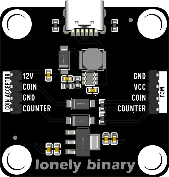
The COIN ACCEPTOR header is 12V, COIN, GND, COUNTER. The MCU header is
GND, VCC, COIN, COUNTER. They are not mirror images, so the pin straight
across the board from 12V is GND — read the silkscreen for each wire rather
than counting rows across.
Wiring, in four lines
- Acceptor red to 12V, black to GND, white to COIN (and grey to COUNTER if you want that output).
- Module GND to your board's GND.
- Module COIN or COUNTER to a GPIO — D2 on an UNO, GPIO27 on an ESP32, GPIO17 on an ESP32-S3, GPIO4 on an ESP32-C3.
- Module VCC to your board's supply pin — last, after the code works and the programming cable is out.
Set the module's rail before any of that: it ships on 3.3 V, and an Arduino UNO needs the 5 V position on the back.
Which output, and which mode
| You want to know | Wire | Library mode |
|---|---|---|
| A coin arrived | COUNTER | COIN_MODE_COUNTER |
| How many coins | COUNTER | COIN_MODE_COUNTER |
| How much money | COIN | COIN_MODE_VALUE |
| Which coin it was | COIN | COIN_MODE_MAPPED |
Value mode needs the coins' pulse values set proportionally to their worth. Mapped mode does not, but it can be confused by two coins dropped in together. Three modes works through both.
Where to start
The handbook below is eleven short articles with a working figure in each. If you have just opened the box, start at one USB-C cable — the adapter is the commonest reason this kit looks broken. If it is wired and counting nothing, it is almost always training. If coins are being missed when people hurry, that is the last page.
When it doesn’t work
- Coins fall straight through and nothing is counted.
- A new acceptor has been trained on no coins at all, including the token in the box, and rejects everything. Training is done on the acceptor itself with its three buttons: get into setup, set a pulse value per coin type, then feed it fifteen of each coin. Nothing about it involves a computer. Train it with real coins walks through what the display says at each step.
- The acceptor restarts, or its display flickers, or coins are rejected at random.
- The supply. The steady draw is modest — 350 mA at 12 V, under an amp at 5 V once the boost converter's losses are counted — but the coin motor pulls hard for a moment every time it runs, and a thin adapter sags instead of following it. A sagging rail resets the acceptor's own computer mid-coin. Use a 5 V 2 A adapter and a short cable, and never a laptop USB port.
- Can I wire the coin acceptor straight to my ESP32 and skip the module?
- No. The acceptor's COIN wire swings the full 12 V, and a 3.3 V input pin is rated to about 3.6 V. Current goes into the chip through a protection diode that was never meant to carry it, and the damage is usually partial rather than total, so the board half works afterwards. The module also supplies the 12 V the acceptor needs, which a level shifter on its own would not.
- My money total is wrong but the coin count is right.
- The pulse values programmed into the acceptor are not proportional to the coins' values, and the sketch is in value mode. Value mode multiplies the pulses in each burst by one fixed rate, so it only works if every coin is set to a proportional count — 5c at 1 pulse, 10c at 2, 25c at 5, $1 at 20, if a pulse is five cents. The quick-start guide's recommended 1 / 3 / 5 counts are for mapped mode, where the count is a label rather than an amount.
- Coins get missed when people drop them in quickly.
- Nothing in the pulse train says a coin has finished, so the library decides a burst has ended after 250 ms of silence. Two coins closer together than that arrive as one burst whose pulse count is the sum. The fix with the most effect is lowering the pulse values so each burst is shorter; moving the signal width switch to Fast helps as well. Value mode is immune to it, because a merged burst still adds up to the right amount of money.
- Which output do I connect, COIN or COUNTER?
- COUNTER if one coin buys one thing — it sends a single pulse per accepted coin and there is nothing to program wrong. COIN if you need the value, because the number of pulses in the burst is the only clue anywhere to which coin it was. The library reads one pin, so wiring both tells it nothing extra. Test with your largest coin: on a coin set to one pulse the two wires look identical, which is how the confusion starts.
- Do I need a separate supply for my microcontroller?
- Not once it is working. The VCC pin on the MCU side feeds your board from the same USB-C adapter. Leave VCC disconnected while you are uploading code, though — your computer is powering the board over USB at that point, and two supplies on one rail is not a state to leave anything in. Connect it after you unplug the programming cable.
- Does it work with MicroPython or a Raspberry Pi?
- The pulse is an ordinary active-low digital signal, so anything that can count falling edges on a pin can read it, a Pi or a Pico in MicroPython included. What we publish and test is the Arduino library, which is where the modes, the debounce and the burst-detection are already written. On another platform you are implementing that yourself — the timings in the handbook are the ones to copy.