
The ESP32-C3 OLED and its three bases
One ESP32-C3 OLED board, three bases it seats on: 2.54 mm pins, push-in terminals or screw terminals. Each base carries the same battery connector, charger and power switch.
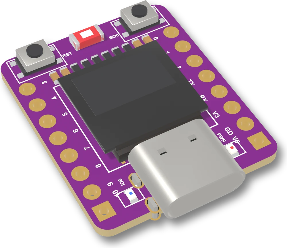 See this board 72 × 40pixel OLEDESP32-C3 OLED Development BoardChip: 160 MHz RISC-V
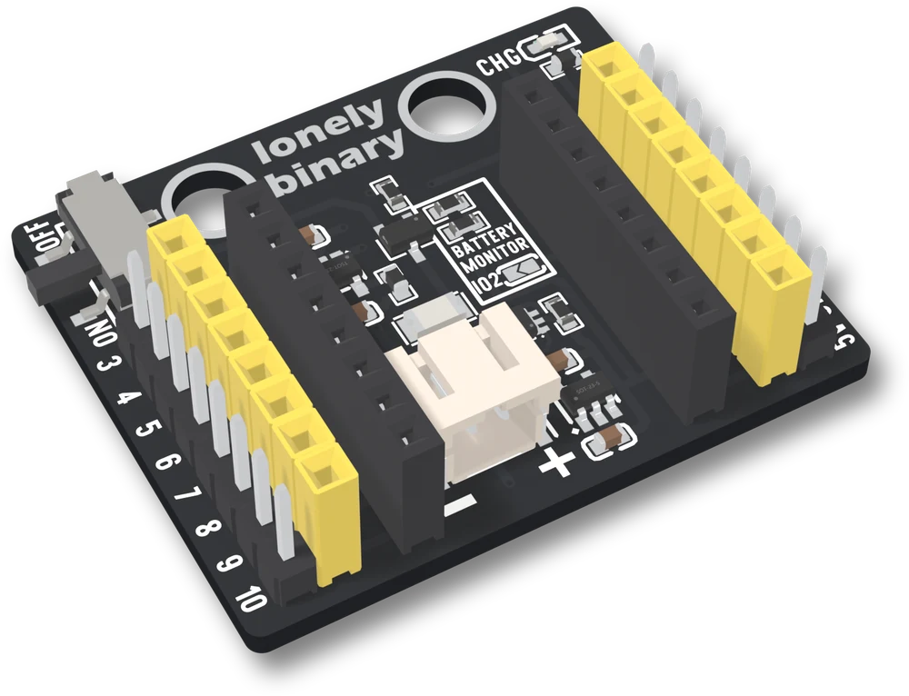 See this board 16GPIO and power, brought outESP32-C3 OLED Expansion Base (2.54 mm)Each side: 8 + 8 pins and sockets at 2.54 mm
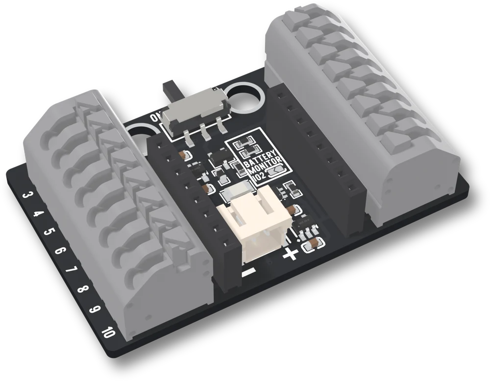 See this board 2 × 8at 3.5 mmESP32-C3 OLED Pluggable Terminal BaseBase size: 53.1 × 32.5 mm
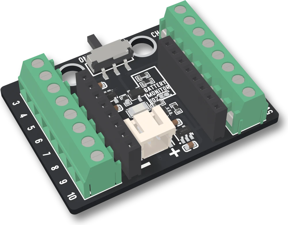 You have this16ESP32-C3 OLED Screw Terminal BaseTerminals: 2 × 8 at 3.5 mm
Build it with your AI
Pick what you want to make, copy, and paste it into ChatGPT, Claude or any assistant. It carries the specs and links to the whole handbook and its own sketches, so the assistant starts from them instead of guessing.
I have a Lonely Binary ESP32-C3 OLED Screw Terminal Base (product code c3screw). Help me with this:

Help me with the handbook's example "Arduino IDE, set up for this board" (https://learn.lonelybinary.com/manuals/c3oled/arduino-ide-setup): get it running on my board, and explain the wiring.

Before you write any code, open these. They are the maker's reference for this exact product:
- The full reference (specs, wiring, every example sketch, troubleshooting): https://learn.lonelybinary.com/ai/c3screw.md
- The handbook's sketch for this task: https://learn.lonelybinary.com/ai/c3screw/hello_c3.ino

Start from that sketch and change only what my task needs. Tell me the wiring, pin by pin, and the board settings.
If you cannot open links, use the facts below. Do not invent pins, voltages or libraries that are not here; ask me instead.

Specifications:
- In the range: The ESP32-C3 OLED board, and three bases it seats on: expansion (2.54 mm pins and sockets), pluggable terminal (3.5 mm push-in) and screw terminal (3.5 mm screw)
- Chip: ESP32-C3FH4, single-core RISC-V up to 160 MHz, 4 MB flash inside the module, 400 kB SRAM, no PSRAM; Wi-Fi 4 and Bluetooth LE; the USB-C socket goes straight to the chip, so there is no driver to install
- Display: 0.42 in OLED, 72 × 40 pixels, SH1106 at I²C address 0x3C, on GPIO 5 (SDA) and GPIO 6 (SCL)
- Holes: 16 on the board and on every base: GPIO 3, 4, 5, 6, 7, 8, 9 and 10 down one side, and GPIO 0, 1, 2, TX (21), RX (20), 3.3 V, ground and 5 V down the other. Six are answering to something before your sketch runs: 5 and 6 (display), 8 (blue LED), 9 (BOO button), 20 and 21 (serial)
- Board size: 25 × 20.5 mm, the two rows of holes 17.78 mm apart
- Edge connectors: Expansion: 8 pins and 8 sockets a side at 2.54 mm, wired together. Pluggable: 2 × 8 push-in terminals at 3.5 mm. Screw: 2 × 8 screw terminals at 3.5 mm
- Base size: Expansion 39.5 × 32.5 mm, screw terminal 44.5 × 32.5 mm, pluggable terminal 53.1 × 32.5 mm
- Tallest part: Measured from the underside of the base: expansion 10.1 mm, screw terminal 10.3 mm, pluggable terminal 14.9 mm
- Mounting: Two 4.8 mm holes, 16 mm apart, on each base
- Battery: JST PH 2.0 two-pin socket for a single 3.7 V lithium cell with a protection circuit; TP4054 linear charger, which takes the cell to 4.2 V; a slide switch between cell and board
- Battery monitor: An open solder jumper marked BATTERY MONITOR and IO2 joins two 100 kΩ resistors across the cell, halved, to GPIO 2. It ships open

Questions people ask:
- Which way round does the board go on a base? Antenna at the power-switch end, USB-C at the battery-connector end. The check that needs no memory: find V5 on the board and 5V on the base and put them at the same end. The board fits turned around just as firmly, and that way the base's 5 V pad meets the pin marked 3, so the battery rail drives three chip pins.
- Which base should I buy? Jumper wires and breadboards: the expansion base, which is also the smallest. Bare wire you change often: the pluggable terminal base, push-in with no screwdriver. Bare wire that has to stay put: the screw terminal base. All three bring out the same sixteen holes and carry the same battery circuit.
- Does a sketch need changing between bases? No. The GPIO numbers belong to the board, and every base brings out the same sixteen holes, so a sketch is the same on all three.
- Why does the base's charge LED not light when I plug in USB? The switch has to be ON, with a battery connected. With the switch OFF the cell is out of the charging circuit, and the charge LED can flicker so fast it looks half-lit. The cell is not charging in that state.
- Why is GPIO 2 not free when I use the battery level? The BATTERY MONITOR jumper connects the divider across the cell to GPIO 2. It ships open so the divider does not draw from the cell; bridge it only if you will read the level, and GPIO 2 is spent from then on.
- Why does the board fail to join my Wi-Fi? The antenna is a ceramic chip a few millimetres long, and at full transmit power the radio overdrives it. The back of every base prints WIFI_POWER_15DBM to 8_5DBM: setting the power down to 8.5 dBm in the sketch is what makes the board stay on a network.
- Do I need a driver? No. The C3 has its own USB peripheral, so the board appears as a serial port with nothing to install. Set USB CDC On Boot to Enabled in the Arduino IDE, or the sketch runs and prints nothing.
Product questions
See what other owners have asked, and read their solutions.
ESP32-C3 OLED Screw Terminal Base
Loading discussions…
Email us or reply to your order, and quote c3screw — that identifies the product. If something is missing from the bag, your order is the record of what shipped.
Point a phone camera at the code and this page opens there. It is the same address as the one printed on your box, so it is also what to show someone you are passing the board to.