
The screw terminal base
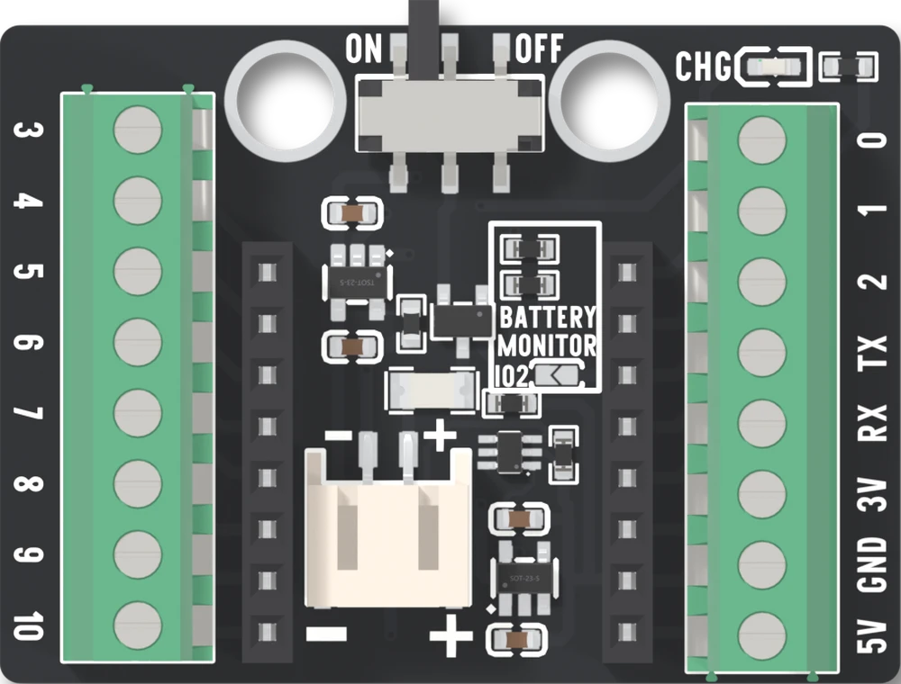
Two blocks of eight screw terminals bring out the sixteen holes, one terminal each. The two blocks are not alike: every way of power is on the right, so a module on the left block fetches its ground from across the board.
Wiring that stays put
The ESP32-C3 OLED board seats in two 8-way sockets down the middle. Beside them, a block of eight screw terminals runs down each long edge at a 3.5 mm pitch, one terminal for each of the board's sixteen holes. This is the base for wiring that will be carried, driven somewhere or left alone: there is nothing to solder, and nothing between a terminal and the board's hole.
The wire goes into the clamp and the screw closes it. A screw that has closed on insulation feels tight and tests dead, so back it out until you can see the clamp open, put bare copper under it, and tighten until the wire will not pull out by hand.
Which terminal is which
Tap a terminal, or pick a GPIO, and the figure says where it is and whether the board already has a use for it.
The label printed beside a terminal is the label printed beside the board's own hole, so nothing here is renumbered. TX is GPIO 21 and RX is GPIO 20, and the terminals printed 3V and 5V are the 3.3 V and the USB 5 V. The two blocks are wired straight to the two sockets, and the net list has no part between a terminal and its hole.
The base's own numbering is the other way up. The right block is a part numbered from the bottom: its way 1 is 5V and its way 8 is GPIO 0. Nothing you wire depends on it, and the silkscreen is the thing to read.
The power is on one side
The right block carries 3V, GND and 5V, one terminal each. The left block carries none: it is GPIO 3 to 10 and nothing else. That is the thing people get wrong, because a block of eight terminals looks like a header, and a header usually has a ground in it.
So a module on the left block takes its supply from the right: a wire from the 3V terminal across the board, and another from GND. There is also only one GND terminal and one 3V. A project with several modules is easier with a small breadboard or terminal strip that carries the ground and supply, with a single wire from each terminal to it.
Six holes already have a job
GPIO 5 and 6 are the display's bus, GPIO 8 is the blue LED, GPIO 9 is the BOO button, and GPIO 20 and 21 are the serial port. All six are terminals, and a wire on one is on the board's own part too. The sixteen pins says what each costs you. GPIO 2 is free as shipped, and stops being free if the BATTERY MONITOR jumper is bridged.
Size and mounting
The base is 44.5 mm long and 32.5 mm wide, from its mechanical drawing, and its tallest part is a terminal block, 8.7 mm above the board (10.3 mm from the underside, where the terminals' legs stand 1.9 mm proud). There are two mounting holes, 4.8 mm across and 16 mm apart, near the switch end.
The back of the base prints the settings the board needs: the LED on IO8, RX on IO20 and TX on IO21, the display's controller and address, SDA on IO5 and SCL on IO6, and the line Wire.begin(5,6). It also prints WIFI_POWER_15DBM TO 8_5DBM, which is the Wi-Fi article's advice to turn the transmit power down.
When it does not work
The left block is eight signals and nothing else: GPIO 3 to 10. 3V, GND and 5V are on the right block, one terminal each. A module wired to the left block needs its supply and its ground wired across from the right block, or taken from a breadboard that both blocks feed.
The clamp has closed on insulation, or beside the copper. Back the screw out until you can see the clamp open, put bare copper under it with no insulation inside the clamp, tighten until the wire will not move, and tug it. A screw that has closed on insulation feels tight and tests dead.
Those two terminals are the display's bus: GPIO 5 is SDA and GPIO 6 is SCL, with the screen already on them. Another I2C device with a different address belongs there. An LED, a button or a sensor's data line does not, and it will corrupt what the screen is sent.
The BATTERY MONITOR jumper has been bridged, and the terminal printed 2 is joined to the middle of the battery divider. It reads half the battery voltage, whatever you wired to it. The jumper ships open; cut or scrape the solder bridge to free the pin again.
Check which way round it went before anything else, with the cable and the battery out. Turned around, the base's 5V, ground and 3V3 meet the board's 3, 4 and 5 pins. The seating page has the one-label check.
A potentiometer on the right block, read on GPIO 1, with the three wires and the sketch that checks them.
A first build on the screw terminal base →Edit this page — content/books/c3oled/the-screw-terminal-base.mdx
Questions about this product
See what other owners have asked, and read their solutions.
This page covers several products. Choose yours to see the right discussions.
Discuss this article
Ask about this page. The answer stays here, on the page it belongs to, for whoever hits the same wall next.