This lesson uses: Arduino UNO R3 board, TinkerBlock TK02 RGB LED module, jumper wires (or breadboard). Learn to control RGB with analogWrite() on three channels; outcome: cycle through red, green, blue, white, yellow, purple, cyan, about 1 s each.
1. Wiring
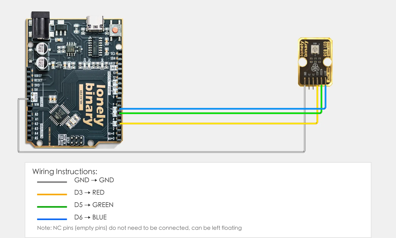
Connect TK02 RGB LED to Arduino (each color on a PWM pin):
- GND → Arduino GND
- RED → Arduino D3 (PWM)
- GREEN → Arduino D5 (PWM)
- BLUE → Arduino D6 (PWM)
- NC leave unconnected
2. New sketch
- Arduino IDE: File → New (or Ctrl/Cmd + N) to create a blank sketch
- Confirm board and port are selected (same as Lesson 01)
- Type the code below into the default
setup()andloop()yourself
3. Program structure
Same as last lesson: two fixed blocks setup() and loop().
setup(): Tell the board “pins 3, 5, 6 for RGB LED (PWM)”; start serial (optional); runs once.loop(): Keep repeating “red → green → blue → white (all three) → yellow (R+G) → purple (R+B) → cyan (G+B) → repeat”.
Different brightness ratios give different colors; you’ll see red, green, blue, white, yellow, purple, cyan in turn.
4. Code to write
Type the code below line by line into setup() and loop() (do not copy-paste; typing it yourself helps you remember):
#define RED_PIN 3      // Red on D3
#define GREEN_PIN 5    // Green on D5
#define BLUE_PIN 6     // Blue on D6

void setup() {
  pinMode(RED_PIN, OUTPUT);     // All three PWM outputs
  pinMode(GREEN_PIN, OUTPUT);
  pinMode(BLUE_PIN, OUTPUT);
  Serial.begin(9600);
  Serial.println("RGB color mixing program started");
}

void loop() {
  // Red (red only)
  analogWrite(RED_PIN, 255);
  analogWrite(GREEN_PIN, 0);
  analogWrite(BLUE_PIN, 0);
  Serial.println("Red");
  delay(1000);

  // Green (green only)
  analogWrite(RED_PIN, 0);
  analogWrite(GREEN_PIN, 255);
  analogWrite(BLUE_PIN, 0);
  Serial.println("Green");
  delay(1000);

  // Blue (blue only)
  analogWrite(RED_PIN, 0);
  analogWrite(GREEN_PIN, 0);
  analogWrite(BLUE_PIN, 255);
  Serial.println("Blue");
  delay(1000);

  // White (all max)
  analogWrite(RED_PIN, 255);
  analogWrite(GREEN_PIN, 255);
  analogWrite(BLUE_PIN, 255);
  Serial.println("White");
  delay(1000);

  // Yellow (red + green)
  analogWrite(RED_PIN, 255);
  analogWrite(GREEN_PIN, 255);
  analogWrite(BLUE_PIN, 0);
  Serial.println("Yellow");
  delay(1000);

  // Purple (red + blue)
  analogWrite(RED_PIN, 255);
  analogWrite(GREEN_PIN, 0);
  analogWrite(BLUE_PIN, 255);
  Serial.println("Purple");
  delay(1000);

  // Cyan (green + blue)
  analogWrite(RED_PIN, 0);
  analogWrite(GREEN_PIN, 255);
  analogWrite(BLUE_PIN, 255);
  Serial.println("Cyan");
  delay(1000);
}
Program notes
Overall idea: Three channels with analogWrite(0–255); one channel 255 = pure color; multiple channels = mix: R+G=yellow, R+B=purple, G+B=cyan, all 255=white. Cycle through (R,G,B) sets to show multiple colors.
| Code | In this lesson |
|---|---|
analogWrite(RED_PIN, 255) | That channel full; 0 = off |
| Multiple channels | R+G=yellow, R+B=purple, G+B=cyan, R=G=B=255=white |
5. Hands-on
- After entering the code, click Verify (✓) to compile
- Click Upload (→) to upload to the board
- Watch TK02: red, green, blue, white, yellow, purple, cyan in order, then repeat
- Try yourself:
- Other colors (e.g. orange: R255, G128, B0)
- Use a
forloop for color fade - Mix your favorite color
Expected result: As in the figure.
Proceed to Lesson 21.
6. Common issues
| Symptom | What to do |
|---|---|
| Wrong colors | Check wiring: RED→D3, GREEN→D5, BLUE→D6 |
| Mix not obvious | Try different values, e.g. 128 instead of 255 |
Edit this page — content/guides/tinkerblock-workshop/20-rgb-color-mixing.mdx
Questions about this product
See what other owners have asked, and read their solutions.
RGB LED
Loading discussions…
Discuss this article
Ask about this page. The answer stays here, on the page it belongs to, for whoever hits the same wall next.