Specifications
| Type | RGB LED output block, common cathode, active high |
|---|---|
| LED | Amicc A-SC667R6AGHB1W, 5 × 5 mm PLCC-6: red, green and blue chips behind a white diffuser, 120° viewing angle |
| Resistors | 3 × 1 kΩ, one per colour, between each header pin and its LED's anode |
| Current | About 3.1 mA red and 2.2 mA green or blue from a 5 V pin; about 1.4 mA and 0.5 mA from 3.3 V. Estimated from the datasheet, not measured |
| Pins to wire | 4 of the 6: GND, RED, GREEN and BLUE. The two NC pins are connected to nothing on the board |
| Header | 6-pin right-angle male, 2.54 mm pitch: GND, NC, NC, RED, GREEN, BLUE, with GND on the square pad |
| Supply | None of its own. Each colour pin powers its own LED, so the colours follow your board's logic voltage |
| Colour control | PWM on each colour pin, with analogWrite on any PWM-capable pin |
| Board | 22.4 × 30.4 mm, two 4.8 mm mounting holes 16 mm apart |
| In the box | 1 × TK02 block. It also ships inside the TinkerBlock kits |
What it is
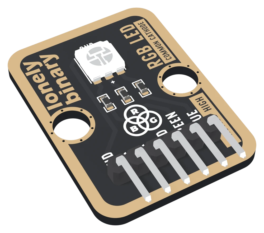
Three LEDs in one small square package: a red, a green and a blue, each with its own 1 kΩ resistor on the board and its own pin on the header. Drive one and you get that colour. Drive two or three with PWM and the white diffuser blends them into one mixed colour.
It is common cathode and active high. The LED's three cathodes are joined to GND on the board, so a colour lights when its pin is HIGH. Sketches written for a common-anode LED, which send 255 minus each value, show the opposite colours here.
Three colours, three currents
There is no supply pin: each colour pin powers its own LED. The same 1 kΩ resistor sits on every colour, but red needs about 0.9 V less than green and blue, so it keeps more voltage for its resistor and draws more current:
| Your board | Pin voltage | Red | Green, blue |
|---|---|---|---|
| Arduino Uno | 5 V | about 3.1 mA | about 2.2 mA |
| ESP32, ESP32-S3, Pico | 3.3 V | about 1.4 mA | about 0.5 mA |
All of them are far inside what any pin may supply. They are estimates from the LED's datasheet rather than measurements. The difference between the two rows is why a colour that looks right on an Uno leans pink on a 3.3 V board.
Which pin is which
Component side up, header at the bottom, reading left to right:
| GND | to your board's GND | the square pad: count from here |
| NC | nothing | not connected on the board |
| NC | nothing | not connected on the board |
| RED | to a PWM pin | through R6, 1 kΩ, to the red LED |
| GREEN | to a PWM pin | through R7, 1 kΩ, to the green LED |
| BLUE | to a PWM pin | through R8, 1 kΩ, to the blue LED |
The back prints TK02 RGB LED and MIXES RED, GREEN, BLUE instead of pin names. Turned over, the square pad is on the right, and it is still GND.
Wiring, in four lines
- GND to your board's GND.
- RED to D9 on an Uno, GPIO 25 on an ESP32, GPIO 4 on an ESP32-S3, GP13 on a Pico.
- GREEN to D10, GPIO 26, GPIO 5 or GP14.
- BLUE to D11, GPIO 27, GPIO 6 or GP15.
All of those are PWM pins. Leave both NC pins unconnected. The classic ESP32 does not use GPIO 4, 5 and 6 like the S3, because its flash chip owns GPIO 6 to 11.
Example
// Uno: 9, 10, 11. ESP32: 25, 26, 27. ESP32-S3: 4, 5, 6. Pico: 13, 14, 15.
const int RED_PIN = 4;
const int GREEN_PIN = 5;
const int BLUE_PIN = 6;

// 0 is off, 255 is full. Common cathode: no "255 -" anywhere.
void setColour(int r, int g, int b) {
  analogWrite(RED_PIN, r);
  analogWrite(GREEN_PIN, g);
  analogWrite(BLUE_PIN, b);
}

void setup() {
  pinMode(RED_PIN, OUTPUT);
  pinMode(GREEN_PIN, OUTPUT);
  pinMode(BLUE_PIN, OUTPUT);
}

void loop() {
  setColour(255, 0, 0);    // red
  delay(1000);
  setColour(0, 255, 0);    // green
  delay(1000);
  setColour(0, 0, 255);    // blue
  delay(1000);
}from machine import Pin, PWM
import time
# ESP32: 25, 26, 27. ESP32-S3: 4, 5, 6. Pico: 13, 14, 15.
red = PWM(Pin(4), freq=1000)
green = PWM(Pin(5), freq=1000)
blue = PWM(Pin(6), freq=1000)
def set_colour(r, g, b):
# 0 is off, 255 is full. Common cathode: no "255 -" anywhere.
red.duty_u16(r * 257)
green.duty_u16(g * 257)
blue.duty_u16(b * 257)
while True:
set_colour(255, 0, 0) # red
time.sleep(1)
set_colour(0, 255, 0) # green
time.sleep(1)
set_colour(0, 0, 255) # blue
time.sleep(1)Where to start
The handbook below is nine short articles, each with a working figure. The first colour is the whole build in four wires and a short sketch.
If you only read one, read why equal numbers are not white. It is the question everyone asks of an RGB LED, and the answer is not the one most people expect.
And if your colours look pink on an ESP32, why 3.3 V turns it pink works out why, and what numbers to use instead.
When it doesn’t work
- One colour never comes on.
- Almost always the wrong pin. Each colour pin has to go to the pin the sketch names for it, by the GPIO number printed beside the pin on your board. Then count from the square pad: GND, NC, NC, RED, GREEN, BLUE. One hole over puts a colour on an NC pin that goes nowhere.
- Why is 255, 255, 255 not white?
- Each number sets a fraction of that LED's own maximum, and the three maximums give very different amounts of light. White needs mostly green light, about a third red and very little blue. Worked out from the datasheet, green at 255 with red near 167 and blue near 122 is a starting point from a 5 V board; trim by eye from there.
- My white turns pink on an ESP32.
- Green and blue take about 2.8 V and a 3.3 V pin leaves them only about 0.5 V, so they lose about three quarters of their current. Red takes about 1.9 V and loses only about half. Turn red down, to about half of what it was on a 5 V board, and trim by eye.
- Do I need to add resistors?
- No. Each colour already has a 1 kΩ resistor on the board, and it keeps the current to a few milliamps even from a 5 V pin. Adding more only makes the colours dimmer.
- Everything is the opposite colour.
- The sketch was written for a common-anode LED and sends 255 minus each value. The TK02 is common cathode and active high: 0 is off and 255 is full. Remove the subtraction.
- Which pins should I use?
- Three PWM pins. D9, D10 and D11 on an Uno; GPIO 25, 26 and 27 on an ESP32; GPIO 4, 5 and 6 on an ESP32-S3; GP13, GP14 and GP15 on a Pico. Not GPIO 6 on a classic ESP32: GPIO 6 to 11 belong to its flash chip.