This lesson uses: Arduino UNO R3 board, TinkerBlock TK29 Analog To Digital Signal module (optional), jumper wires (or breadboard). Learn ADC (Analog-to-Digital Conversion); outcome: serial prints A0 analog value (0–1023) and D2 digital value (0 or 1) together so you see continuous vs discrete, multi-level vs two-level.
1. What is ADC?
ADC (Analog-to-Digital Converter) turns a continuous analog signal (e.g. voltage) into a discrete digital value.
- Analog: continuously varying (e.g. any voltage between 0V and 5V)
- Digital: only two states (HIGH/LOW, or 0/1)
Arduino’s analogRead() uses the ADC to convert 0–5V into 0–1023.
The TK29 is not itself an ADC, whatever its name suggests. It holds a comparator: it compares the analog voltage with a threshold set by its blue knob and gives one bit, HIGH or LOW, on DIG. That makes it a good way to see both kinds of signal side by side.
2. Wiring (optional)
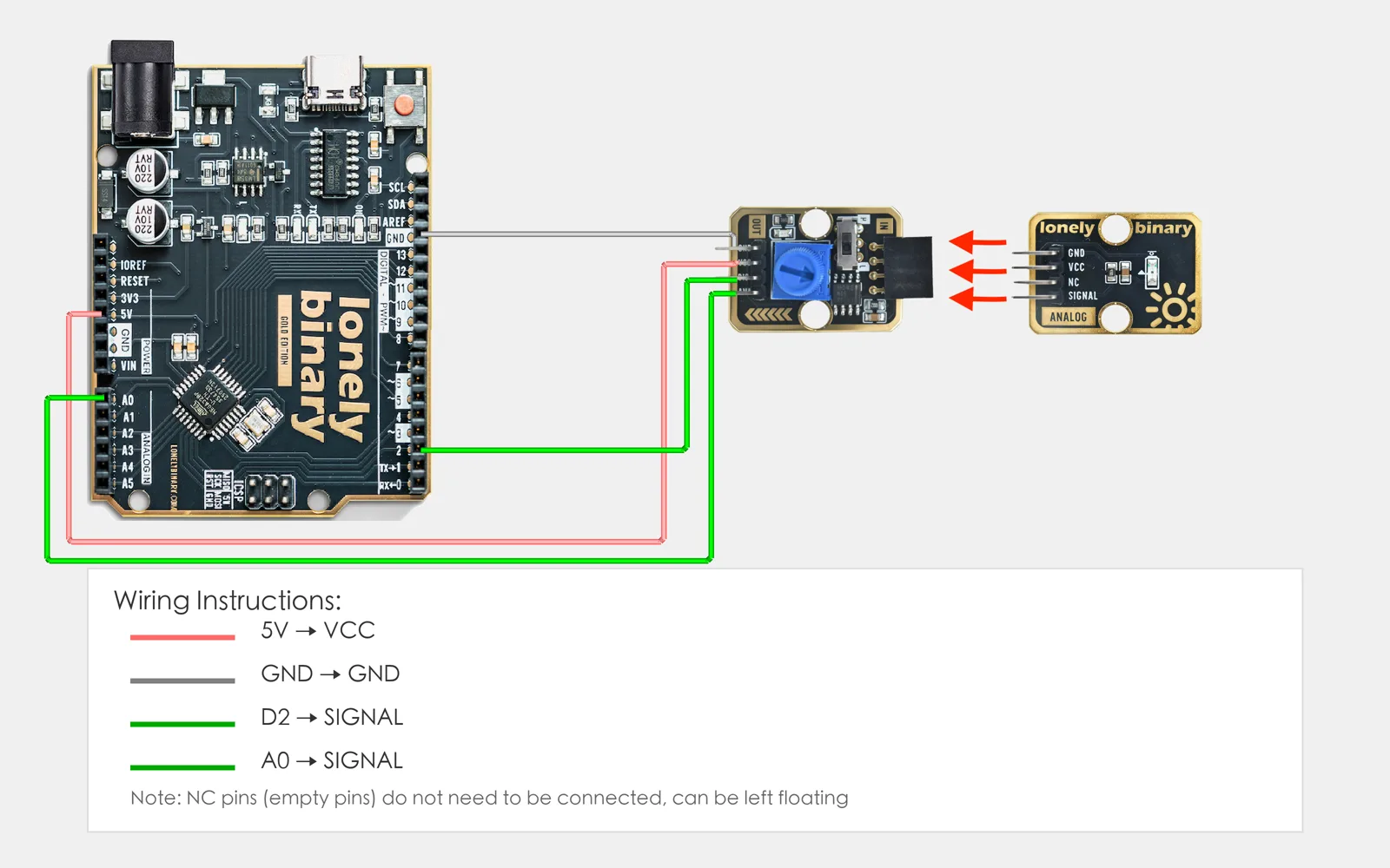
To test with TK29:
- GND → Arduino GND
- VCC → Arduino 5V
- ANA → Arduino A0
- DIG → Arduino D2
The TK29's OUT header has no NC pin: it reads GND, VCC, DIG, ANA from the square pad. ANA is not an input. It carries the voltage of the analog block pushed into the TK29's IN socket (a TK08 potentiometer is the easiest), so put one there first; with the socket empty, both readings wander. Set the TK29's slide switch to H, so DIG is 1 while ANA is above the knob.
3. New sketch
- Arduino IDE: File → New (or Ctrl/Cmd + N) to create a blank sketch
- Confirm board and port are selected (same as Lesson 01)
- Type the code below into the default
setup()andloop()yourself
4. Program structure
Same as last lesson: two fixed blocks setup() and loop().
setup(): Start serial; runs once.loop(): Keep repeating “read analog and digital → print to serial → wait → repeat”.
On the serial you’ll see one column 0–1023 changing smoothly and one column only 0 and 1—the difference is clear.
5. Code to write
Type the code below into setup() and loop() (do not copy-paste; typing it yourself helps you remember):
// ADC demo: compare analog (continuous) vs digital (high/low only)
void setup() {
  Serial.begin(9600);
  Serial.println("ADC concept demo");
}

void loop() {
  int analogVal = analogRead(A0);   // A0 via ADC → 0-1023, maps to 0V-5V
  int digitalVal = digitalRead(2);  // D2 digital: only HIGH(1) or LOW(0)

  Serial.print("Analog: ");
  Serial.print(analogVal);
  Serial.print(" | Digital: ");
  Serial.println(digitalVal);

  delay(200);   // One line every 200 ms
}
Program notes
Overall idea: A0 gets analog (e.g. potentiometer or TK29 ANA), D2 gets digital (e.g. switch or TK29 DIG). analogRead(A0) converts 0–5V to 0–1023 via the ADC; digitalRead(2) only compares to a threshold and gives 0 or 1. Printing both shows: analog changes continuously, digital only 0 or 1.
Why 0–1023: Uno’s ADC is 10-bit: 2^10 = 1024 levels, coded 0–1023. 0V→0, 5V→1023, linear in between. Digital input is not quantized, only high/low, so two states only.
TK29: If connected, its ANA is continuous voltage and DIG is high/low, matching the two reads; without it, A0/D2 can be floating or other sensors (analog may drift, digital often fixed).
| Code | In this lesson |
|---|---|
analogRead(A0) | Read A0 voltage; ADC gives 10-bit 0–1023 for 0V–5V |
digitalRead(2) | Read D2; above threshold ≈ 1(HIGH), else 0(LOW); no in-between |
| ADC vs digital | Analog: continuous voltage → discrete levels (1024); digital: high/low only |
| 10-bit resolution | Uno ADC output 0–1023; resolution ≈ 5V/1024 ≈ 4.9 mV |
6. Hands-on
- After entering the code, click Verify (✓) to compile
- Click Upload (→) to upload to the board
- Open Serial Monitor (Tools → Serial Monitor, baud 9600)
- Watch: analog 0–1023, digital only 0 or 1
- (Optional) If TK29 is connected, compare ANA and DIG
Expected result:
Serial monitor:
ADC concept demo
Analog: 512 | Digital: 0
Analog: 523 | Digital: 0
Analog: 678 | Digital: 1
...
Proceed to Lesson 30.
Edit this page — content/guides/tinkerblock-workshop/29-adc-concept.mdx
Questions about this product
See what other owners have asked, and read their solutions.
Analog to Digital Signal
Loading discussions…
Discuss this article
Ask about this page. The answer stays here, on the page it belongs to, for whoever hits the same wall next.