Specifications
| Type | Threshold switch: a comparator between an analog block and your board. DIG is HIGH or LOW; it returns no number |
|---|---|
| Comparator | ON Semiconductor LM393, one of its two comparators. Offset 5 mV at most, response about 1.3 µs (datasheet typical) |
| Threshold | Set by a 10 kΩ single-turn trimmer from VCC to GND: any share of VCC, set with a small screwdriver |
| Switch | Slide switch printed H and L. H: DIG is HIGH while the input is higher than the knob. L: while it is lower |
| Input range | 0 to VCC − 1.5 V at 25 °C: about 1.8 V from 3.3 V, about 3.5 V from 5 V. Keep the knob below that; the input may go higher |
| Output | DIG, open collector with a 10 kΩ pull-up to VCC. ANA, the IN block's SIGNAL passed straight through |
| Indicator | Red LED with 1 kΩ from VCC to DIG: lit while DIG is LOW, the opposite of the output |
| Hysteresis | None on the board. A slow or noisy input makes DIG chatter at the threshold; add hysteresis in the sketch |
| Supply | 3.3 V or 5 V on VCC, the same as your board's logic: DIG is pulled up to VCC. It also powers the block in IN |
| Current | Under 1 mA while DIG is HIGH and about 2 to 4 mA while it is LOW, plus the block in IN. Worked out, not measured |
| Headers | IN: 4-way right-angle socket for a TinkerBlock sensor. OUT: 4-pin right-angle male, 2.54 mm pitch, GND, VCC, DIG, ANA, GND on the square pad |
| Board | 22.4 × 30.4 mm, two 4.8 mm mounting holes 16 mm apart |
| In the box | 1 × TK29 block. It also ships inside the TinkerBlock kits |
What it is
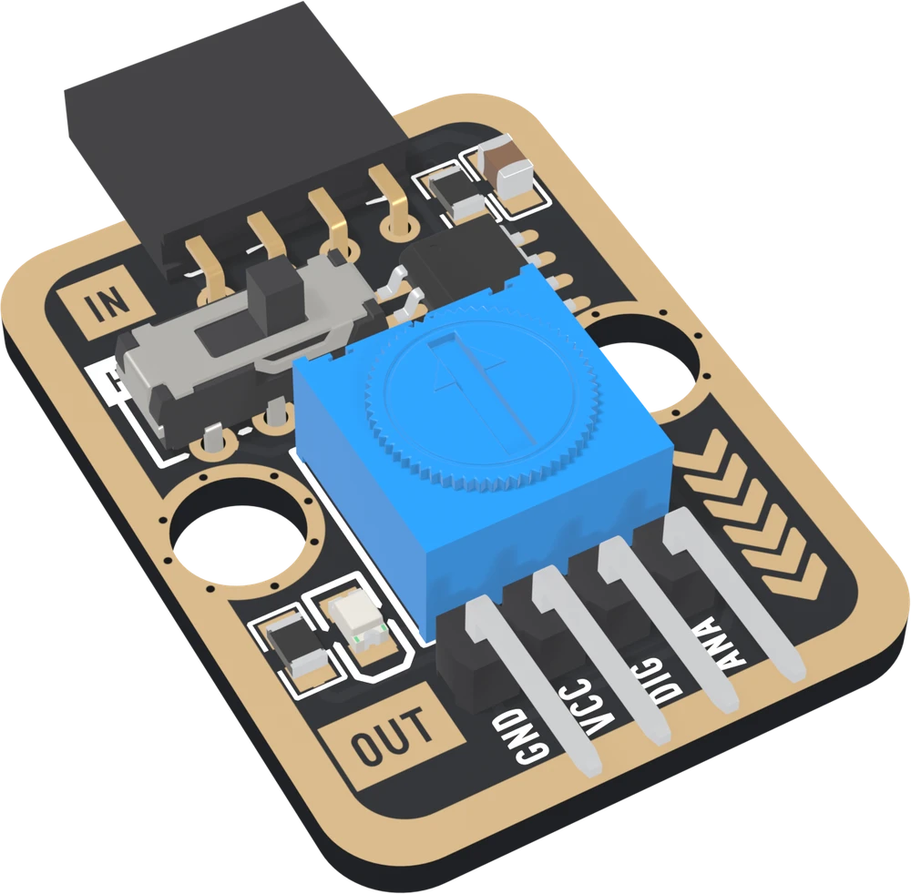
A comparator between two blocks. An analog block, such as a TK08 potentiometer or a TK20 light sensor, plugs into the IN socket at the top. Your board wires to the OUT header at the bottom. Between them, an LM393 compares the block's voltage with the one set by the blue knob and says which is higher, as HIGH or LOW on DIG.
The name promises an analog-to-digital converter, and it is one only in the
narrowest sense: it turns a voltage into one bit. analogRead returns a
number; this returns yes or no. So the block also passes the input's voltage
through on ANA, and your board can read both: the decision from DIG, the
number from ANA.
The page this replaces got several things wrong. ANA is not an input to connect a sensor to; the sensor goes in IN. DIG is not always HIGH above the threshold; the slide switch decides. The inputs do not work all the way to VCC. And the output does not give a clean edge by itself: with no hysteresis, a slow input makes it chatter.
The four things to know
The switch. H: DIG is HIGH while the input is higher than the knob. L: while it is lower.
The light. The red LED lights while DIG is LOW, the opposite of the output.
The range. The LM393 compares from 0 V to about VCC − 1.5 V. From 3V3 that is 1.8 V, and the top 45 % of the knob is out of range. The input may go higher, as long as the knob stays inside.
No hysteresis. Near the threshold a slow input makes DIG flicker. Read ANA and switch at two lines in the sketch.
Which pin is which
OUT, parts up, reading left to right. The names are printed along the pins:
| GND | to your board's GND | the square pad: count from here |
| VCC | to 3V3 or 5V | your board's logic voltage |
| DIG | to a digital input | the comparator's answer |
| ANA | to an analog input, optional | the IN block's SIGNAL, passed through |
IN takes a TinkerBlock sensor in its own order, GND, VCC, NC, SIGNAL, and prints no names. Its third position is connected to nothing, and DIG sits where a block's NC would be.
Wiring, in four lines
- GND to your board's GND.
- VCC to 5V on an Uno, 3V3 on an ESP32, ESP32-S3 or Pico. DIG is pulled up to VCC, so it must match.
- DIG to a digital pin: D2 on an Uno, GPIO 25 on an ESP32, GPIO 7 on an ESP32-S3, GP15 on a Pico.
- ANA to an analog pin if you want the number: A0 on an Uno, GPIO 34 on an ESP32, GPIO 4 on an ESP32-S3, GP26 on a Pico.
Then push an analog block into IN.
Example
// DIG_PIN, then ANA_PIN.
// Uno: 2 and A0. ESP32: 25 and 34. ESP32-S3: 7 and 4. Pico: 15 and 26.
const int DIG_PIN = 2;
const int ANA_PIN = A0;

void setup() {
  Serial.begin(115200);
  pinMode(DIG_PIN, INPUT);          // the block has its own pull-up
}

void loop() {
  Serial.print("DIG ");
  Serial.print(digitalRead(DIG_PIN));   // the decision
  Serial.print("   ANA ");
  Serial.println(analogRead(ANA_PIN));  // the number behind it
  delay(250);
}import sys
import time
from machine import ADC, Pin
# DIG_PIN, then ANA_PIN.
# ESP32: 25 and 34. ESP32-S3: 7 and 4. Pico: 15 and 26.
dig = Pin(7, Pin.IN) # no pull: the block has its own
adc = ADC(Pin(4))
if sys.platform == "esp32":
adc.atten(ADC.ATTN_11DB) # the full range, to about 3.1 V
while True:
print("DIG", dig.value(), " ANA", adc.read_u16())
time.sleep_ms(250)Where to start
The handbook below is eleven short articles, each with a working figure. The first read is the whole build: a TK08 in IN, four wires, and DIG and ANA side by side. H and L explains the switch.
For a lamp that comes on at dusk, a light switch puts a TK20 in the socket. If DIG flickers, read chatter and hysteresis; if the knob seems dead past halfway, the input range.
When it doesn’t work
- Is it an analog-to-digital converter?
- Not in the sense analogRead is. A converter returns a number; this returns one bit, HIGH or LOW, from a comparator. It turns an analog voltage into a digital signal by comparing it with a threshold you set on the knob. It passes the voltage through on ANA as well, so your board's own ADC can still read the number.
- Where does the sensor go?
- Into the IN socket at the top, parts facing the same way as the TK29's. Its GND, VCC, NC and SIGNAL land on the socket's four positions in order, and it takes its power from the TK29. ANA on the OUT header is not an input: it is that block's SIGNAL carried through to your board.
- What do H and L mean?
- When DIG is HIGH. At H, while the input is Higher than the knob; at L, while it is Lower. The switch swaps the comparator's two inputs, so the threshold stays where it is and the answer turns over.
- Why is the LED on when DIG is LOW?
- It is wired from VCC through 1 kΩ onto DIG, so it only has a voltage across it when the comparator pulls DIG down. Lit means LOW. It is handy for setting the knob without a board.
- Past halfway, the knob stops working.
- From 3.3 V the LM393 compares only up to about 1.8 V, which is about 55 % of the knob's travel. Above that the threshold is out of range. From 5 V the range reaches about 3.5 V, 70 % of the travel.
- DIG flickers when the input is near the threshold.
- There is no hysteresis on the board, and the comparator answers in about a microsecond, so every wobble of a slow input across the knob flips DIG. Read ANA in the sketch and switch at two lines, one either side of the knob.