This lesson uses: Arduino UNO R3 board, TinkerBlock TK06 Rotary Encoder module, TinkerBlock TK01 XL LED module, jumper wires (or breadboard). Use the rotary encoder for rotation direction and button; outcome: turn encoder to adjust LED brightness (CW brighter, CCW dimmer), press encoder button to toggle LED (off/on), and when turning on again the previous brightness is restored.
1. Wiring
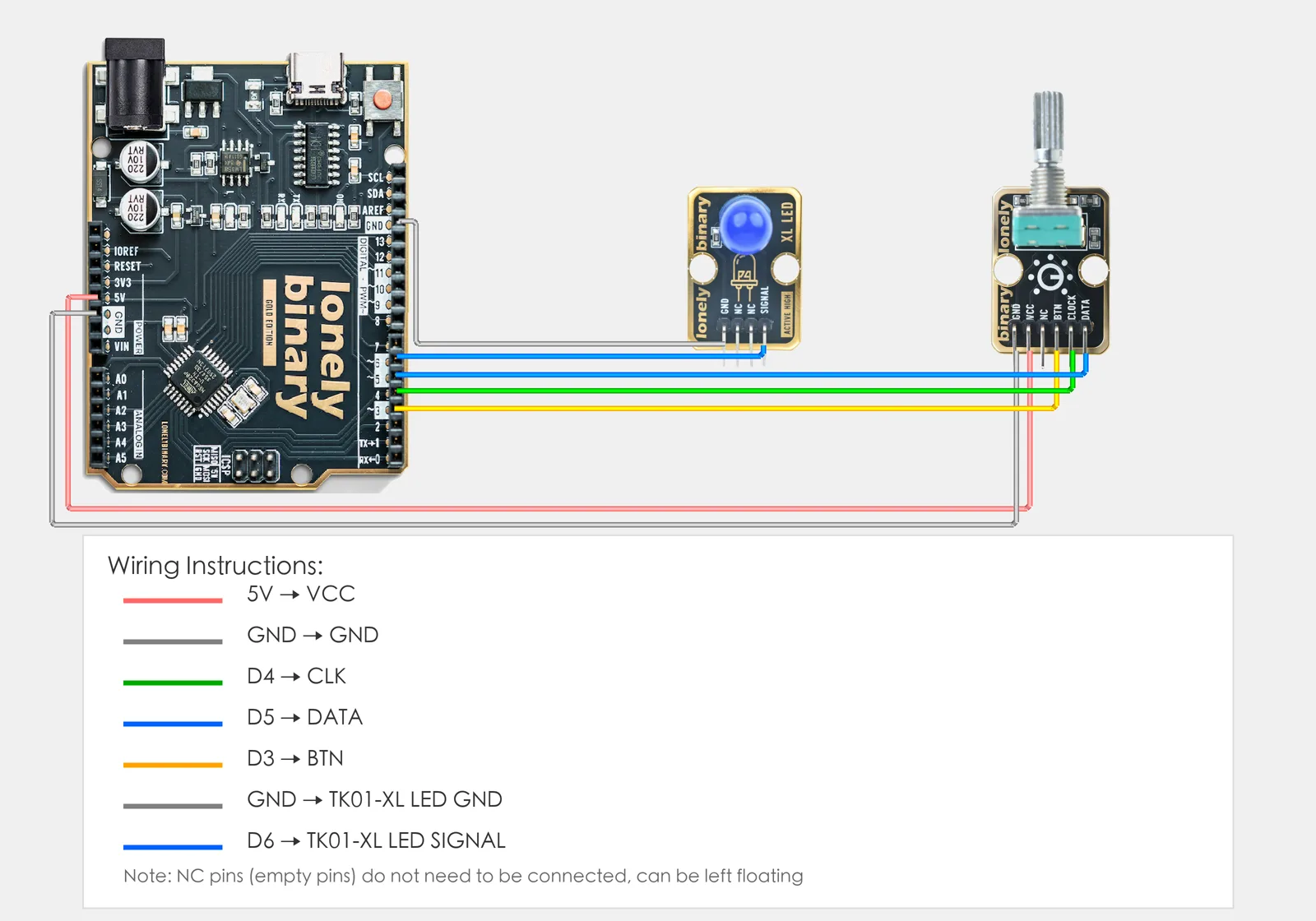
- TK06 Rotary Encoder: VCC → 5V, GND → GND, CLK → D4, DATA → D5, BTN → D3
- TK01 LED: GND → GND, SIGNAL → D6 (PWM pin)
2. New sketch
- Arduino IDE: File → New (or Ctrl/Cmd + N) to create a blank sketch
- Confirm board and port are selected (same as Lesson 01)
- Type the code below into the default
setup()andloop()yourself
3. Program structure
Same as last lesson: two fixed blocks setup() and loop().
setup(): Tell the board “D4, D5 for encoder, D3 for button, D6 for LED”; start serial; runs once.loop(): Keep repeating “detect rotation → change brightness (when LED on) → detect button (press to toggle) → wait → repeat”.
Turn encoder to change brightness; one press turns LED off, another turns it on and restores the last brightness.
4. Code to write
Type the code below into setup() and loop() (do not copy-paste; typing it yourself helps you remember):
// Pins: encoder CLK/DATA for direction, BTN for button, LED on PWM pin
#define CLK_PIN 4    // Encoder CLK on D4
#define DATA_PIN 5   // Encoder DATA on D5
#define BTN_PIN 3    // Encoder button BTN on D3
#define LED_PIN 6    // LED on D6 (PWM)

int brightness = 128;           // Current LED brightness (0-255)
int savedBrightness = 128;      // Stored when off; restore when on again
bool ledOn = true;             // LED state: true=on, false=off
int lastClkState = HIGH;       // Previous CLK for edge detection

void setup() {
  pinMode(CLK_PIN, INPUT_PULLUP);   // Encoder CLK, internal pull-up
  pinMode(DATA_PIN, INPUT_PULLUP);   // Encoder DATA
  pinMode(BTN_PIN, INPUT_PULLUP);    // Button: pressed = LOW
  pinMode(LED_PIN, OUTPUT);

  Serial.begin(9600);
  lastClkState = digitalRead(CLK_PIN);  // Initial CLK to avoid false edge
  analogWrite(LED_PIN, brightness);     // Start at brightness
}

void loop() {
  int clkState = digitalRead(CLK_PIN);

  // Rotation: CLK change = one step
  if (clkState != lastClkState) {
    if (clkState == LOW && ledOn) {
      int dataState = digitalRead(DATA_PIN);

      if (dataState == LOW) {
        brightness = min(255, brightness + 20);  // CW: brighter, cap 255
        Serial.println("CW - brightness up");
      } else {
        brightness = max(0, brightness - 20);   // CCW: dimmer, min 0
        Serial.println("CCW - brightness down");
      }

      analogWrite(LED_PIN, brightness);
    }
    lastClkState = clkState;
  }

  // Button: LOW when pressed. Toggle on/off; save brightness when off, restore when on
  if (digitalRead(BTN_PIN) == LOW) {
    ledOn = !ledOn;
    if (ledOn) {
      brightness = savedBrightness;
      analogWrite(LED_PIN, brightness);
      Serial.println("Button - LED on");
    } else {
      savedBrightness = brightness;  // Save before turning off
      brightness = 0;
      analogWrite(LED_PIN, 0);
      Serial.println("Button - LED off");
    }
    delay(200);   // Debounce
  }

  delay(10);   // Short delay for stable read
}
Program notes
Overall idea: In loop() read CLK, DATA, and BTN; use CLK change to detect one step and DATA to tell CW/CCW and adjust brightness; on button press flip ledOn, save brightness when turning off and restore when turning on.
Direction: When the encoder turns one step, CLK and DATA change in order. This code reads DATA only on CLK falling edge (HIGH→LOW): DATA LOW = CW, DATA HIGH = CCW, so no double count and stable direction.
Button and memory: ledOn is the on/off state. On button (BTN LOW), ledOn = !ledOn. When turning off, save brightness to savedBrightness then set 0; when turning on, copy savedBrightness back to brightness. Rotation only changes brightness when ledOn is true.
Debounce: delay(200) after button press to avoid multiple triggers.
| Code | In this lesson |
|---|---|
#define CLK_PIN 4 etc. | Pin constants; change here if you rewire |
INPUT_PULLUP | Input with internal pull-up; BTN is HIGH when not pressed, LOW when pressed |
lastClkState | Previous CLK; compare with current to detect edge = one step |
clkState == LOW && ledOn | Only adjust brightness on CLK edge when LED is on |
min(255, brightness + 20) | Cap at 255; max(0, brightness - 20) caps at 0 |
ledOn = !ledOn | Toggle on/off |
savedBrightness | Store brightness when off; restore when on |
delay(200) | Simple button debounce |
5. Hands-on
- After entering the code, click Verify (✓) to compile
- Click Upload (→) to upload to the board
- Open Serial Monitor (Tools → Serial Monitor, baud 9600)
- Turn TK06 (when LED on): CW = brighter, CCW = dimmer
- Press encoder button: once = off, again = on (previous brightness restored)
Expected result: As in the figure.
Proceed to Lesson 31.
Edit this page — content/guides/tinkerblock-workshop/30-rotary-encoder.mdx
Questions about this product
See what other owners have asked, and read their solutions.
This page covers several products. Choose yours to see the right discussions.
Discuss this article
Ask about this page. The answer stays here, on the page it belongs to, for whoever hits the same wall next.