Specifications
| Type | Incremental quadrature rotary encoder with a push switch, no end stops |
|---|---|
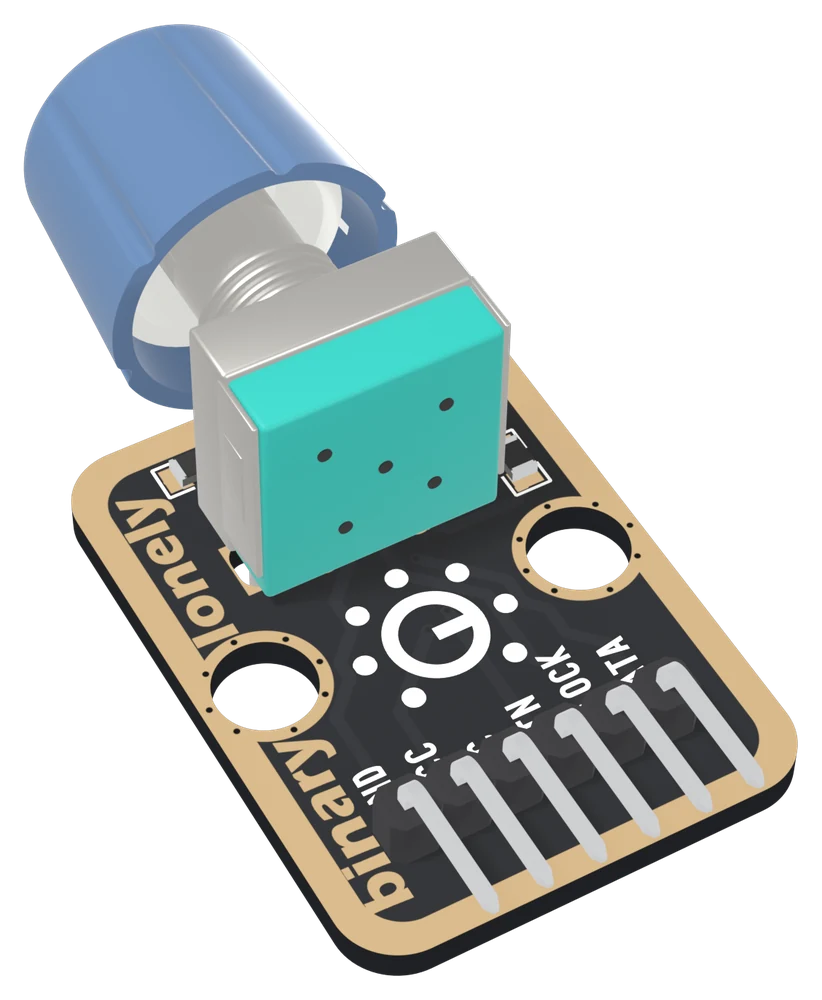
| Encoder | EC11-type, horizontal, Ø6 mm shaft on an M7 bushing, blue knob. Most EC11 parts give 20 clicks a turn; count yours |
| Pull-ups | 10 kΩ from CLOCK and from DATA to VCC, with 100 nF from each to GND: a 1 ms filter. Both rest HIGH and go LOW while their contact is closed |
| Push switch | Joins BTN to VCC, with a 10 kΩ pull-down to GND. Released reads LOW, pushed reads HIGH |
| Supply | 3.3 V or 5 V on VCC. CLOCK, DATA and BTN all reach VCC, so use 3V3 beside an ESP32, ESP32-S3 or Pico and 5V beside an Uno |
| Pins to wire | 5 of the 6: GND, VCC, BTN, CLOCK and DATA. NC is connected to nothing on the board |
| Header | 6-pin right-angle male, 2.54 mm pitch: GND, VCC, NC, BTN, CLOCK, DATA, with GND on the square pad |
| Board | 22.4 × 30.4 mm, two 4.8 mm mounting holes 16 mm apart; 15.43 mm to the top of the knob |
| In the box | 1 × TK06 block. It also ships inside the TinkerBlock kits |
What it is
A knob with no end stops. Inside it, two contacts close and open a quarter of a cycle apart as the shaft turns; each pulls its line, CLOCK or DATA, LOW while it is closed, and a 10 kΩ pull-up holds it HIGH while it is open. The direction is in which of the two falls first, and the distance is how many times they do. Push the knob in and a third switch pulls BTN HIGH.
Unlike a potentiometer, it reports change, not position, so it suits a menu,
a volume that should not jump when the program starts, or any value with more
range than one turn. The catch is in the reading. A sketch that polls the
pins from a loop() with a delay() in it counts perfectly when turned
gently and loses count, or counts backwards, when someone flicks it. The
handbook below shows why and fixes it with an interrupt.
Each rotation line also has a 100 nF capacitor to GND, which with the pull-up makes a 1 ms filter against contact bounce. It helps; it does not make bounce impossible.
VCC is the level of all three signals
| Your board | VCC to | CLOCK and DATA at rest | BTN pushed |
|---|---|---|---|
| Arduino Uno | 5V | 5 V | 5 V |
| ESP32, ESP32-S3, Pico | 3V3 | 3.3 V | 3.3 V |
Never 5V beside a 3.3 V board. With VCC unconnected, CLOCK and DATA float and the count wanders on its own.
Which pin is which
Knob side up, header at the bottom, reading left to right:
| GND | to your board's GND | the square pad: count from here |
| VCC | to 3V3 or 5V | your board's logic voltage |
| NC | nothing | not connected on the board |
| BTN | to a digital input | HIGH while the knob is pushed in |
| CLOCK | to a digital input | rests HIGH, LOW while its contact is closed |
| DATA | to a digital input | the same, a quarter of a cycle away |
The back prints TK06 ROTARY ENCODER and ROTATES TO PICK SETTINGS instead of pin names. Turned over, the square pad is on the right, and it is still GND.
Wiring, in five lines
- GND to your board's GND.
- VCC to 5V on an Uno, 3V3 on an ESP32, ESP32-S3 or Pico.
- CLOCK to D2 on an Uno, GPIO 25 on an ESP32, GPIO 4 on an ESP32-S3, GP13 on a Pico.
- DATA to D3 on an Uno, GPIO 26 on an ESP32, GPIO 5 on an ESP32-S3, GP14 on a Pico.
- BTN to D4 on an Uno, GPIO 27 on an ESP32, GPIO 6 on an ESP32-S3, GP15 on a Pico.
Leave NC unconnected. Set all three pins to INPUT: the pull-ups and the
pull-down are already on the board.
Example
// CLOCK, DATA and BTN, as GPIO numbers.
// Uno: 2, 3, 4. ESP32: 25, 26, 27. ESP32-S3: 4, 5, 6. Pico: 13, 14, 15.
const int CLOCK_PIN = 4;
const int DATA_PIN = 5;

long count = 0;
int lastClock = HIGH;

void setup() {
  Serial.begin(115200);
  pinMode(CLOCK_PIN, INPUT);    // the block has its own pull-ups
  pinMode(DATA_PIN, INPUT);
}

void loop() {
  int clockLevel = digitalRead(CLOCK_PIN);
  if (clockLevel != lastClock) {
    if (clockLevel == LOW) {    // CLOCK has just fallen
      if (digitalRead(DATA_PIN) == HIGH) count++;   // CLOCK first
      else count--;                                 // DATA first
      Serial.println(count);
    }
    lastClock = clockLevel;
  }
}from machine import Pin
# CLOCK and DATA. ESP32: 25, 26. ESP32-S3: 4, 5. Pico: 13, 14.
clock = Pin(4, Pin.IN) # no pull: the block has its own
data = Pin(5, Pin.IN)
count = 0
last_clock = 1
while True:
level = clock.value()
if level != last_clock:
if level == 0: # CLOCK has just fallen
count += 1 if data.value() == 1 else -1
print(count)
last_clock = levelIf it counts down when you turn clockwise, swap count++ and count--.
Where to start
The handbook below is ten short articles, each with a working figure. The first count is the whole build in five wires and a few lines.
If the count goes wrong when you turn the knob quickly, read why polling misses steps and then counting with an interrupt.
And before plugging it into an ESP32, VCC sets all three levels is the one page that protects the board.
When it doesn’t work
- Does BTN read HIGH or LOW when pushed?
- HIGH. The switch in the shaft joins BTN to VCC, and a 10 kΩ pull-down holds it at 0 V the rest of the time. Released reads LOW, pushed reads HIGH. Sketches written for encoder boards whose switch is pulled up test for LOW and get this block backwards.
- INPUT or INPUT_PULLUP?
- INPUT on all three pins. CLOCK and DATA already have 10 kΩ pull-ups on the board, and BTN has a pull-down that the chip's pull-up would fight. In MicroPython, Pin(pin, Pin.IN) with no pull argument.
- Should VCC go to 3V3 or 5V?
- To your board's logic voltage: 3V3 on an ESP32, ESP32-S3 or Pico, 5V on an Uno. CLOCK and DATA rest at VCC through their pull-ups, so 5V beside a 3.3 V board holds its pins past their rating the whole time, not only when you turn.
- The count jumps around or goes backwards when I turn it fast.
- The sketch is reading the pins too late: a delay() or a slow print in loop(). Count in an interrupt on CLOCK, or on both pins with a state table. On an Uno, CLOCK and DATA need to be on D2 and D3, its two external-interrupt pins.
- It counts the wrong way.
- Not a fault. Which contact leads when turned clockwise depends on the part. Swap the + and - in the sketch, or swap the CLOCK and DATA pin numbers.
- One click gives two or four counts.
- The sketch counts more edges than the part has clicks. Counting one fall of CLOCK per cycle gives one count a click on many EC11 parts; a state table counts four steps a cycle and divides by four. Turn one full turn and compare the count with the clicks you felt.
- Do I need to add capacitors to the phases?
- No. 100 nF from CLOCK and from DATA to GND is already fitted. With the 10 kΩ pull-ups that is a 1 ms filter that swallows the shortest bounces. It helps; a state table in the sketch deals with what gets past it.