Specifications
| Type | Single LED output block, active high |
|---|---|
| LED | 10 mm blue, through-hole, 12.5 mm tall above the board |
| Resistor | 150 Ω, fitted between the LED's cathode and GND. The part is printed 1500 |
| Current | About 13 mA from a 5 V pin, about 2 mA from a 3.3 V pin. Measured on the bench; the LED takes about 3.0 V |
| Pins to wire | 2 of the 4: GND and SIGNAL. The two NC pins are connected to nothing on the board |
| Header | 4-pin right-angle male, 2.54 mm pitch: GND, NC, NC, SIGNAL, with GND on the square pad |
| Supply | None of its own. The pin driving SIGNAL powers the LED, so brightness follows your board's logic voltage |
| Brightness control | PWM on SIGNAL, with analogWrite on any PWM-capable pin |
| Board | 22.4 × 30.4 mm, two 4.8 mm mounting holes 16 mm apart |
| In the box | 1 × TK01 block. It also ships inside the TinkerBlock kits |
What it is
One LED, one resistor, and a header. The LED is blue with a 10 mm lens. The resistor beside it is 150 Ω, and it is the reason the block exists: a bare LED wired straight to a pin draws whatever current the pin can give, and eventually takes the pin with it.
It is active high. Set SIGNAL HIGH and it lights, LOW and it goes out. The front of the board says ACTIVE HIGH and the back says GLOWS WHEN HIGH, so there is no doubt which way round it works.
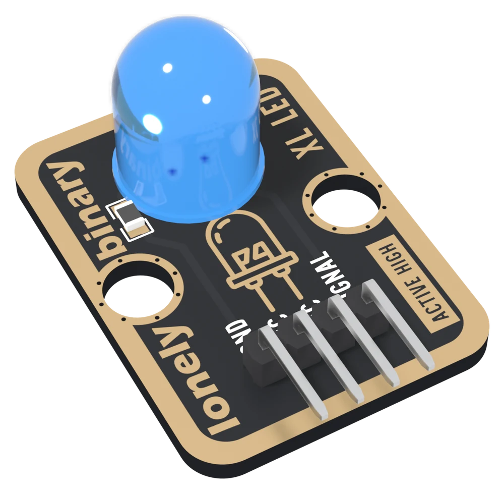
There is no supply pin
Most blocks have a VCC pin. This one doesn't: the pin you drive is the LED's power. That has one consequence worth knowing before you plug it in. The LED takes about 3.0 V, and only what is left over drives current through the resistor, so it is much brighter from a 5 V board than from a 3.3 V one:
| Your board | Pin voltage | Left for the resistor | Current |
|---|---|---|---|
| Arduino Uno | 5 V | about 2.0 V | about 13 mA |
| ESP32, ESP32-S3, Pico | 3.3 V | about 0.3 V | about 2 mA |
Both are within what the pin may supply, and both are plainly lit. The currents are bench measurements of one board; the LED has no datasheet.
Which pin is which
LED side up, header at the bottom, reading left to right:
| GND | to your board's GND | the square pad: count from here |
| NC | nothing | not connected on the board |
| NC | nothing | not connected on the board |
| SIGNAL | to a digital pin | HIGH lights the LED |
The back prints TK01 XL LED and GLOWS WHEN HIGH instead of pin names. Turned over, the square pad is on the right, and it is still GND.
Wiring, in two lines
- GND to your board's GND.
- SIGNAL to a digital pin: D9 on an Uno, GPIO 4 on an ESP32 or ESP32-S3, GP15 on a Pico. Those are all PWM pins, so the same wiring also dims it.
Leave both NC pins unconnected. No resistor to add, no library to install.
Example
// The GPIO number SIGNAL is wired to. Uno: 9. ESP32, ESP32-S3: 4. Pico: 15.
const int LED_PIN = 4;

void setup() {
  pinMode(LED_PIN, OUTPUT);     // without this, HIGH is only a weak pull-up
}

void loop() {
  digitalWrite(LED_PIN, HIGH);  // the pin supplies the LED's current
  delay(500);
  digitalWrite(LED_PIN, LOW);
  delay(500);
}from machine import Pin
import time
# The GPIO number SIGNAL is wired to. ESP32, ESP32-S3: 4. Pico: 15.
led = Pin(4, Pin.OUT)
while True:
led.on() # HIGH: the pin supplies the LED's current
time.sleep(0.5)
led.off()
time.sleep(0.5)Where to start
The handbook below is nine short articles, each with a working figure. The first blink is the whole build in two wires and five lines.
If you only read one, read what the resistor is for. It is the reason the block exists, and the reason not to wire a bare LED to a pin.
And if it looks dim on your ESP32, why it is dimmer on 3.3 V works out why that is normal and what the real options are.
When it doesn’t work
- The LED never lights.
- Almost always the wrong pin. SIGNAL has to go to the pin your sketch names, and the number in pinMode is the GPIO number printed beside the pin on your board, not its position along the header. Then check GND: without it there is no loop. Then count from the square pad, because one pin over puts SIGNAL on an NC pin that goes nowhere.
- Why is it dimmer on my ESP32 than on an Uno?
- The LED takes about 3.0 V whatever the pin gives, so a 3.3 V pin leaves only 0.3 V for the 150 Ω resistor: about 2 mA, against about 13 mA from an Uno's 5 V pin. It is normal and not a fault. The block has no supply pin of its own, so its brightness always follows the logic voltage of the board driving it.
- Do I need to add a resistor?
- No. The 150 Ω resistor is already on the board, between the LED and GND, and it keeps the current inside what any common board's pin may supply. Adding another in series only makes the LED dimmer.
- What are the two NC pins for?
- Nothing on this board. They are in no net at all. Every TinkerBlock block has the same four-pin header so the same cable fits all of them, and this block only needs two of the four.
- It lights but will not turn off.
- The pin is being held HIGH by something else. A serial transmit pin idles HIGH, and a pin wired to 3V3 or 5V instead of a GPIO is always on. Move SIGNAL to a plain digital pin such as D9 on an Uno or GPIO 4 on an ESP32.
- Can it be dimmed?
- Yes, with PWM. analogWrite(pin, 0) is off and analogWrite(pin, 255) is fully on, on any PWM-capable pin. On an Uno those are pins 3, 5, 6, 9, 10 and 11. For a fade that looks even, send the values through a small correction table rather than stepping evenly.