One header, four adapters
The four adapters have no parts on them. Each one is copper that joins the mainboard's 26 positions to one development board's pins, so KEY1 is always position 4 and lands on GPIO4, D2, GP16 or BCM4 depending on which adapter is in.
Four boards of copper
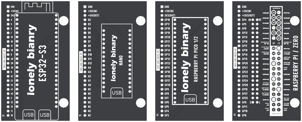
The mainboard's header has 26 positions and each has one job: position 4 is KEY1, position 19 is COIN, position 26 is the screen's chip select. An adapter joins those positions to whichever pins of its development board were free and suitable. That is all it does. There are no components on it.
So the mainboard never changes, and the pin your code reads does. Every example in the kit's repository starts with a list of those pins for its board, taken from this table.
Which adapter
| Your board | Adapter | Buttons and coin | Screen | Code |
|---|---|---|---|---|
| ESP32-S3, DevKitC-1 layout | ESP32-S3 | Yes | Yes | Arduino |
| Classic Arduino Nano | NANO | Yes | No | Arduino |
| Raspberry Pi Pico or Pico 2 | PICO 1/2 | Yes | Yes | MicroPython |
| Raspberry Pi Zero 2 W | ZERO | Yes | Yes | Python |
Which way up
The header is right-angled on both boards. The adapter plugs in edge to edge
and lies flat beside the mainboard, not on top of it. THIS SIDE FACES UP is
printed beside the adapter's row of pins; with that side up, GND on the
adapter meets GND on the mainboard, at the USB-C end.
Seat the development board on the adapter with its USB socket where the adapter's outline draws one. Check GND and the supply pins at both ends before you power anything. Swap adapters only with every cable unplugged: "HotSwap" means the adapters are interchangeable, not that they can be changed live.
When it does not work
The adapter is laid out for the 44-pin DevKitC-1 pattern: two rows of 22, with 3V3, 3V3, RST at one end of one row and 5V, GND at the other. Lonely Binary's ESP32-S3 board and Espressif's own DevKitC-1 fit. Boards that call themselves ESP32-S3 but have a different pin count or order do not, however close they look.
The classic one, with an ATmega328P and 5 V logic, and the clones of it. Not a Nano Every, a Nano 33 or a Nano ESP32: they share the outline but not the pins or the voltages the kit's code assumes.
The adapter is on the header one position out. Unplug everything at once: one position out also puts the mainboard's 5 V onto the board's ground or its 3.3 V pin. Line up GND with GND, at the USB-C end of the mainboard and the GND end of the adapter's row.
They land on BCM14 and BCM15, which Raspberry Pi OS gives to the serial console. Run sudo raspi-config, go to Interface Options, then Serial Port, say no to the login shell and no to the serial hardware, and reboot.
Which one programs the board, which one powers the coin acceptor, and what happens with both.
Two USB sockets →Edit this page — content/books/arcade/one-header-four-adapters.mdx
Questions about this product
See what other owners have asked, and read their solutions.
HotSwap Arcade Kit: Buttons, Joystick and Coin Acceptor for ESP32-S3, Nano, Pico and Zero 2 W
Loading discussions…
Discuss this article
Ask about this page. The answer stays here, on the page it belongs to, for whoever hits the same wall next.