Specifications
| In the box | 1 mainboard, 4 adapters, 1 joystick, 10 arcade buttons, 14 button cables, 1 coin acceptor with its cable, 4 mounting screw sets and pin headers |
|---|---|
| Adapters | 4 adapters: ESP32-S3 (DevKitC-1 layout), classic Arduino Nano (ATmega328P), Raspberry Pi Pico or Pico 2, Raspberry Pi Zero 2 W. Copper only, no components |
| Supply | USB-C, 5 V, power only: the socket has no data contacts. 2 A or more |
| Acceptor supply | About 12 V, made on the mainboard by an MT3608 boost converter. Only the acceptor socket carries it |
| Inputs | 14 switch inputs, KEY1 to KEY10 and UP, DOWN, LEFT, RIGHT, on 2-pin sockets. Each has a 10 kΩ pull-down; pressed reads HIGH |
| Logic level | V(MCU), the adapter's own rail: 3.3 V on the ESP32-S3, Pico and Zero 2 W adapters, 5 V on the Nano. No level shifter needed |
| Coin signals | COIN and COUNTER, active low. Each is pulled up to V(MCU) through 10 kΩ behind an SS24 diode that keeps the acceptor's 12 V out |
| Header | 26 positions, 2.54 mm, right-angle. The adapter plugs in edge to edge and lies flat beside the mainboard |
| Screen | 15-way 1.0 mm FPC, 9 contacts wired. Not connected on the Nano adapter. The kit's display examples drive an ILI9488 |
| Code | Arduino C++ on the ESP32-S3 and Nano, MicroPython on the Pico, Python on the Zero 2 W. Open source on GitHub |
What it does
The kit is an arcade control panel that plugs into four kinds of development board. The mainboard has sockets for ten buttons, a joystick's four switches, a coin acceptor and a screen, and brings all of them to one 26-pin header. An adapter joins that header to your board.
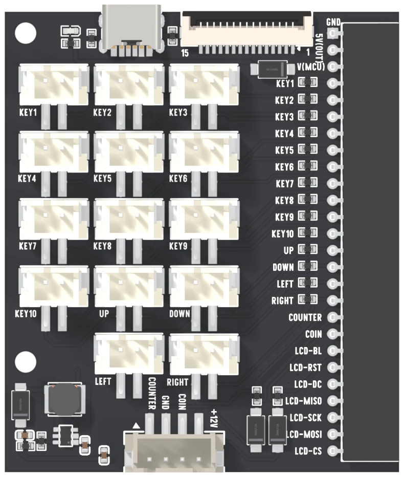
It also makes the coin acceptor's 12 V from the 5 V on its USB-C socket, so one supply runs everything.
The four adapters
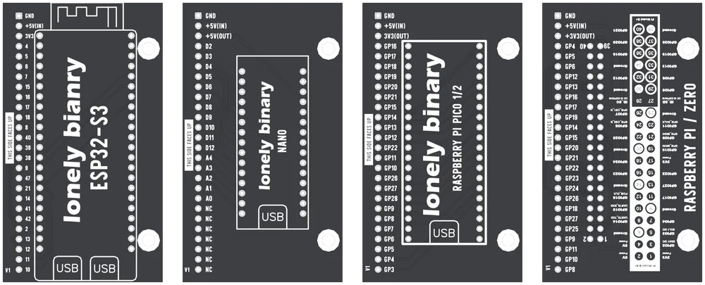
| Mainboard | ESP32-S3 | Nano | Pico | Zero 2 W |
|---|---|---|---|---|
| KEY1 | GPIO4 | D2 | GP16 | BCM4 |
| KEY2 | GPIO5 | D3 | GP17 | BCM5 |
| KEY3 | GPIO6 | D4 | GP18 | BCM6 |
| KEY4 | GPIO7 | D5 | GP19 | BCM12 |
| KEY5 | GPIO15 | D6 | GP20 | BCM13 |
| KEY6 | GPIO16 | D7 | GP21 | BCM16 |
| KEY7 | GPIO17 | D8 | GP15 | BCM17 |
| KEY8 | GPIO18 | D9 | GP14 | BCM19 |
| KEY9 | GPIO8 | D10 | GP13 | BCM14 |
| KEY10 | GPIO40 | D11 | GP12 | BCM15 |
| UP | GPIO39 | D12 | GP22 | BCM20 |
| DOWN | GPIO38 | A4 | GP11 | BCM21 |
| LEFT | GPIO9 | A3 | GP10 | BCM22 |
| RIGHT | GPIO47 | A2 | GP26 | BCM23 |
| COUNTER | GPIO21 | A1 | GP27 | BCM24 |
| COIN | GPIO14 | A0 | GP28 | BCM26 |
| LCD-BL | GPIO41 | — | GP9 | BCM18 |
| LCD-RST | GPIO42 | — | GP8 | BCM27 |
| LCD-DC | GPIO2 | — | GP7 | BCM25 |
| LCD-MISO | GPIO13 | — | GP6 | BCM9 |
| LCD-SCK | GPIO12 | — | GP5 | BCM11 |
| LCD-MOSI | GPIO11 | — | GP4 | BCM10 |
| LCD-CS | GPIO10 | — | GP3 | BCM8 |
Power in two sentences
The development board's own USB programs it and powers the buttons. The mainboard's USB-C powers everything, the coin acceptor included, but carries no data. See Two USB sockets.
Where to start
Run the input monitor with one button on KEY1: Press a button. Then the joystick, then the coins, in the handbook's order.
When it doesn’t work
- Which adapter do I need?
- The one named on your development board: ESP32-S3 for a DevKitC-1-style ESP32-S3 board, NANO for a classic ATmega328P Nano, PICO 1/2 for a Raspberry Pi Pico or Pico 2, ZERO for a Raspberry Pi Zero 2 W. The adapter only reroutes the header; the mainboard is the same for all four.
- Can I program the board through the mainboard's USB-C?
- No. That socket carries power and has no data contacts. Program and read messages through the development board's own USB socket, and use the USB-C socket to power the coin acceptor.
- Do I need a level shifter for the coin acceptor?
- No. The acceptor runs on 12 V but only ever pulls its signal wires to ground. A diode on each line lets that low through and blocks anything higher, and a pull-up holds the pin at your board's own voltage between pulses.
- Why does a pressed button read HIGH?
- Each button joins its input to V(MCU), the development board's own supply, and a 10 kΩ resistor holds the input at ground when it is released. So pressed is HIGH at exactly the voltage your board runs at.
- Can I change adapters with the power on?
- No. HotSwap means the adapters are interchangeable, not that they can be swapped live. Unplug every cable first: an adapter pushed on one position out puts the mainboard's 5 V onto the board's ground or its 3.3 V pin.
- Does it work as a USB or Bluetooth game controller?
- Not out of the box. The examples read the buttons, joystick and coins and print what they see. Turning that into a USB or Bluetooth gamepad is firmware you add, and the kit's examples do not include it.
- Which screens work?
- The kit's display examples are written for an ILI9488 panel. Any SPI panel on a 15-way ribbon with the same contact order will connect, but it needs a driver for its own controller: an ST7735, ST7789 or ST7796 stays white under the ILI9488 code.