
The expansion base
Sixteen holes, each one brought out three ways: an upright pin, a yellow socket beside it, and the socket the board seats in. They are one wire, not three. Six of the thirteen GPIOs are already in use, and the 5V hole is not a battery output.
Pins and sockets, wired together
The expansion base is a 39.5 × 32.5 mm board, 10.1 mm tall measured from its underside, with two 8-way sockets down the middle for the ESP32-C3 OLED board. Every hole of the board comes out beside them: an upright pin on the outer strip of each side, and a yellow socket on the strip next to it.
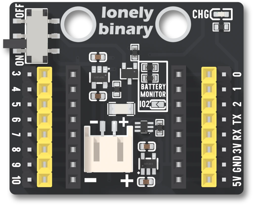
The two rows of the board are 17.78 mm apart, and so are the base's two sockets. The board drops in, and everything on its rows is on the strips.
One hole, three places
Pick a hole. The pin, the yellow socket and the hole in the board's socket light together, because they are one wire. The base has no switch between them and no buffer: a wire on the strip is on the GPIO itself.
Down the left strip the holes are GPIO 3, 4, 5, 6, 7, 8, 9 and 10. Down the
right they are GPIO 0, 1, 2, TX, RX, then 3V, GND and 5V. The silkscreen prints
TX and RX; in code they are GPIO 21 and 20.
What is already spoken for
The base adds nothing to the board's own list. GPIO 5 and 6 are the display,
8 is the blue LED, 9 is the BOO button and 20 and 21 are the serial port, and
the figure marks them. The sixteen pins
says what each costs. The hole printed 2 is free until the BATTERY MONITOR
jumper is bridged, which joins it to a divider across the cell.
The three supplies
3V is the board's own 3.3 V pin. Take a small load from it and do not feed it
from outside while USB is connected. GND is ground, tied to the battery
connector's negative pin. 5V is the board's 5V pin, which is USB's 5 V when
the cable is in.
With only a cell connected, 5V carries nothing. The cell goes through the
switch to a 3.3 V regulator and no further. A part that needs 5 V from the
battery needs a boost converter of its own.
Mounting
Two 4.8 mm holes, 16.00 mm apart, sit along the top edge, 3.76 mm down from it and 11.64 mm and 27.64 mm in from the left. The pins stand 8.5 mm above the board and reach 1.4 mm below it. The mechanical drawing and the 3D model are under Downloads on the base's page.
The one thing people get wrong
Thirty-two holes are not thirty-two signals. There are sixteen, each one twice on the strips, and the second strip is there so that a wire end of either kind fits.
When it does not work
The pin and the socket beside it are the same copper, and so is the matching hole in the board's socket. A wire on the pin and another on the socket go to the same GPIO. Sixteen holes come out, not thirty-two: count eight down each side and ignore the second strip.
The two strips on an edge are different parts. The outer one is upright pins, so it takes a socket-ended jumper. The inner one is a yellow socket, so it takes a pin-ended one. The strips are the same copper, so use whichever your wire's end suits.
The 5V hole is the board's 5V pin, which is USB's 5 V while the cable is in. Nothing on the base makes 5 V from the cell: the cell feeds the 3.3 V regulator and nothing else. For a part that needs 5 V on battery, add a boost converter of your own.
The BATTERY MONITOR jumper beside the connector has been bridged, which joins the hole printed 2 to the middle of a divider across the cell. Open the jumper again to get the pin back. It ships open.
A potentiometer and an LED on four jumper wires, and a sketch that ties them together.
A first build on the expansion base →Edit this page — content/books/c3oled/the-expansion-base.mdx
Questions about this product
See what other owners have asked, and read their solutions.
This page covers several products. Choose yours to see the right discussions.
Discuss this article
Ask about this page. The answer stays here, on the page it belongs to, for whoever hits the same wall next.