
The pluggable terminal base
Two 8-way push-in terminal blocks instead of pin rows: strip a wire, push it in, no solder and no screwdriver. Every hole of the board has one way, the left block carries no power, and there is a single ground way for the lot.
No jumper wires at all
The ESP32-C3 OLED board seats in two 8-way sockets in the middle of the base, and a push-in terminal block runs down each long edge. A stripped wire goes in and a spring holds it. The shop lists this base as the Screwless Terminal Board and the back prints NON-SCREW BOARD. It is the same board.
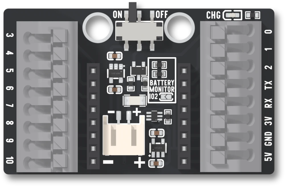
Each block is a Kefa KF250-3.5-8P-1, listed with 3.5 mm between ways. The maker's datasheet gives 22 to 18 AWG wire, 5 A and an 8 to 9 mm strip. The 5 A is the part's rating, not the base's: the power ways carry what the board's own pins supply.
What is on each way
Read it top to bottom, switch end at the top, as the silkscreen prints it. Tap a way.
The left block is GPIO 3, 4, 5, 6, 7, 8, 9 and 10. The right block is GPIO 0, 1, 2, then TX and RX, which are GPIO 21 and 20, then 3V, GND and 5V. Each way goes straight to the hole of the same name on the socket the board sits in, with nothing between them. A way is the hole: the base adds no buffer, no resistor and no LED to any of them.
Six of the thirteen GPIOs already have a job on the board: 5 and 6 are the display, 8 is the blue LED, 9 is the BOO button, and 20 and 21 are the serial port. The sixteen pins says what each costs you.
The two blocks do not match
Everything that is not a GPIO is on the right block. The left block has eight GPIOs and no supply of any kind. So a sensor wired to GPIO 4 needs its ground and its 3.3 V from the other side of the board, and there is one GND way and one 3V way between them.
Push-in ways take one wire each. Run the GND way to a breadboard ground rail and take every return from the rail, the way the first build does.
GPIO 2 is on the right block too, and its way is also joined to one pad of the BATTERY MONITOR jumper beside the battery connector. The jumper ships open, so GPIO 2 is free. Bridge it and a divider across the cell is on that way for good; the battery article has the rest.
Size and mounting
The base is 53.13 by 32.54 mm. Two 4.8 mm mounting holes sit 16.00 mm apart at the switch edge. It stands 14.91 mm tall from its underside, and 13.31 mm of that is above the board: the terminal blocks are the tallest parts on it. The drawing gives the pins 1.90 mm below the board.
The mechanical drawing and the 3D model are on the product page, with the board turning in 3D.
The back
The back prints what the board already says: the blue LED is IO8, RX is IO20
and TX is IO21, the OLED is an SH1106 72 by 40 at 0x3C, and the I²C pins are
SDA IO5 and SCL IO6, with Wire.begin(5,6) written out. It also prints
WIFI_POWER_15DBM TO 8_5DBM, the transmit power the radio has to be turned
down to; that is a later article.
When it does not work
A push-in way holds a bare conductor, so the stripped length matters: the maker's datasheet gives 8 to 9 mm. Shorter leaves insulation under the spring; longer leaves copper showing next to the neighbouring way, 3.5 mm away. It lists 22 to 18 AWG wire, so a thinner jumper wire may not be held. Tug each wire after it goes in; if it moves, it never seated. To free a wire, press the grey tab on the way and pull.
The left block is GPIO 3 to 10 and nothing else: there is no 3V3 and no GND on it. Ground and 3V3 are on the right block, one way each. Run a wire from the GND way to a breadboard ground rail and take every ground from there, because a way takes one wire.
Read the silkscreen, not the part's numbering. Both blocks are printed top to bottom with the switch at the top. The parts are numbered from the bottom, so the right block's way 1 is 5V and its way 8 is GPIO 0, while the left block's way 1 is GPIO 3.
Those ways are the blue LED and the BOO button. Manual download mode needs GPIO 8 high and GPIO 9 low at reset, and a wire that holds either one the wrong way at that moment stops it. Take the wire out, upload, put it back.
It is the USB bus voltage, not a regulator output. Nothing on the base raises the cell to 5 V, so on battery alone that way should read nothing. Power a 5 V load from USB, or use the 3V way for a 3.3 V one.
An LED on GPIO 0 and a button on GPIO 1, wired with three pieces of wire and no tools.
A first build on the pluggable terminal base →Edit this page — content/books/c3oled/the-pluggable-terminal-base.mdx
Questions about this product
See what other owners have asked, and read their solutions.
This page covers several products. Choose yours to see the right discussions.
Discuss this article
Ask about this page. The answer stays here, on the page it belongs to, for whoever hits the same wall next.