Inputs & Controls
Buttons, rotary encoders, touch pads, keypads and joysticks. Debouncing is not optional and nobody tells you that first.
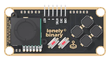
Slim Joystick
A thumb stick and six buttons on one long TinkerBlock board, on six pins. X and Y are two potentiometers, read on analog pins; KEY is the click under the stick, LOW at rest and HIGH when pushed; and all six buttons share BTNS, one analog pin, through a ladder of 10 kΩ resistors that gives each its own voltage. One button reads at a time.
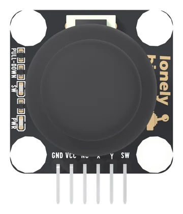
Dual Axis Joystick
A thumbstick on a square TinkerBlock board, on six pins: GND, VCC, NC, X, Y and SW. X and Y are two potentiometers from VCC to GND, read on analog pins; SW is the click under the stick, LOW at rest and HIGH when pressed, with its own pull-down. Every line reaches VCC, so VCC is your board's logic voltage. A PWR light and an SW light show power and each click.
Arcade Coin Acceptor Module Kit, USB-C Powered
A 12 V arcade coin acceptor and the USB-C board that runs it from one cable and hands your microcontroller a logic-level pulse. Up to six coin types, trained on real coins, counted on a single GPIO.
11. Potentiometers
Learn analog input and variables; use analogRead() to read the potentiometer and achieve outcome: when you turn the knob the serial monitor shows 0–1023, and the LED on D9 changes brightness (optional).
15. Multiple Sensors with Serial
Review: combine potentiometer and button; outcome: serial shows potentiometer value and button state (pressed/released) at the same time, and the button still controls the LED.
3. Digital Input: Button
Use the button as digital input; learn to combine digitalRead() with digitalWrite().
30. Rotary Encoder
Use the rotary encoder for rotation direction and button; outcome: turn encoder to adjust LED brightness (CW brighter, CCW dimmer), press encoder button to toggle LED (off/on), and when turning on again the previous brightness is restored.
32. I2C Matrix Keypad
Use Wire library to scan the matrix keypad over I2C; outcome: when you press a key, serial prints the character (0–9, A–D, , #).
34. Joystick
Use analog input to read joystick direction; outcome: serial shows “Up / Left / Down / Right / Press / Center”; when you push a direction the LED is on, when you press or center the LED is off.
39. Project: Button Buzzer LED
Project: one button controls LED and buzzer; outcome: press = LED on and buzzer on, release = LED off and buzzer off.
40. Project: Potentiometer Control
Project: use potentiometer to control output; outcome: knob controls LED brightness (or buzzer pitch), serial shows potentiometer value and brightness/frequency.
42. Project: Joystick Control
Project: joystick direction and button control LED and buzzer; outcome: up = LED on, down = LED off, left = low tone, right = high tone, press = buzzer off; serial prints current action.
5. Serial Monitor Debugging
Learn to use the serial monitor and Serial to print.
7. Latching Button
Learn the latching button and state hold.
9. Touch Sensor
Learn the touch sensor.
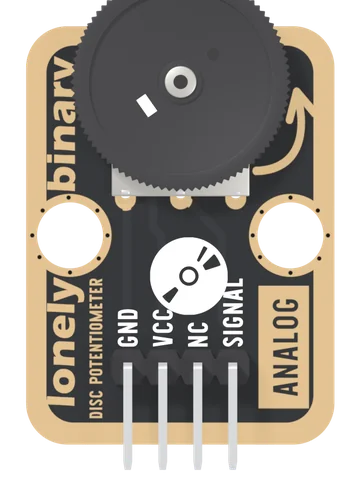
Disc Potentiometer
A 10 kΩ thumbwheel potentiometer wired as a voltage divider: turn the wheel and SIGNAL runs from 0 V to VCC, read by one analog pin. The wheel lies flat and overhangs the board's edge, so a thumb turns it from the side.
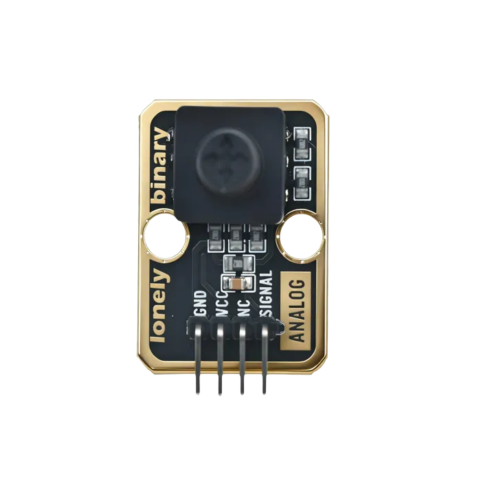
Five-Direction Joystick
Four directions and a centre press wired as five switches — menu navigation with no ADC and no dead-zone maths.
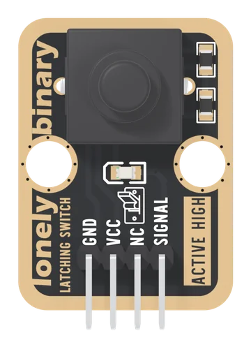
Latching Button
A push-on, push-off switch with its pull-down and a red indicator LED already fitted: one press turns SIGNAL HIGH and it stays HIGH, through a reset or a power cut, until the next press.
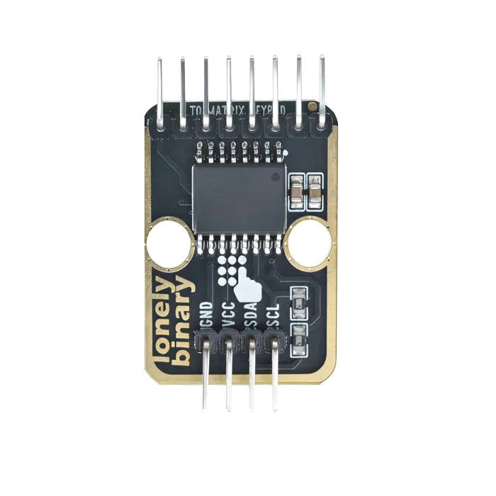
Matrix Keypad with I2C Adapter (4x4, PCF8574)
A 4×4 keypad on two I²C wires instead of eight GPIO pins. The TK85 adapter, the soft and heavy-duty keypads, the two keymaps they need, and how to put two on one bus.
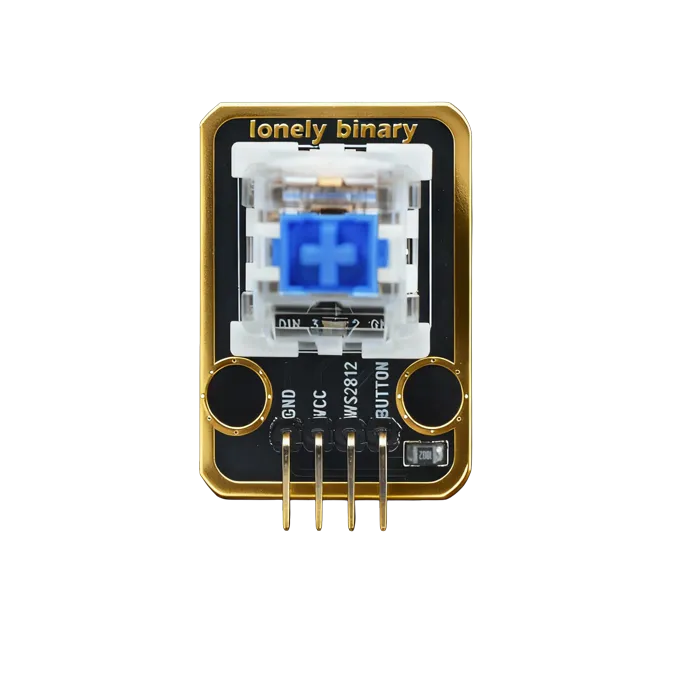
Mechanical Key and LED
A keyboard switch with an LED underneath. Real tactile feedback, and a light to say why it fired — two circuits, not one.
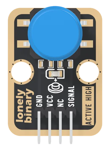
Push Button
A 12 mm momentary push button with its 10 kΩ pull-down and a red press light already fitted: SIGNAL reads HIGH while the button is down. The first input in the kit, and the module that teaches debouncing.
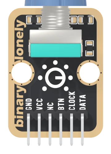
Rotary Encoder
An EC11-type rotary encoder with a push switch in its shaft, its pull-ups, filter capacitors and pull-down already fitted. Two contacts a quarter of a cycle apart give the direction; the program keeps the count. Pushed in, BTN reads HIGH.
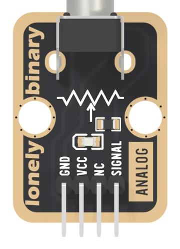
Rotary Potentiometer
A 10 kΩ linear potentiometer with a knob, wired as a voltage divider: SIGNAL gives 0 V to VCC as you turn. A red LED on the wiper glows as you turn up, and it bends the upper part of the reading: hard on 5 V, less on 3.3 V.
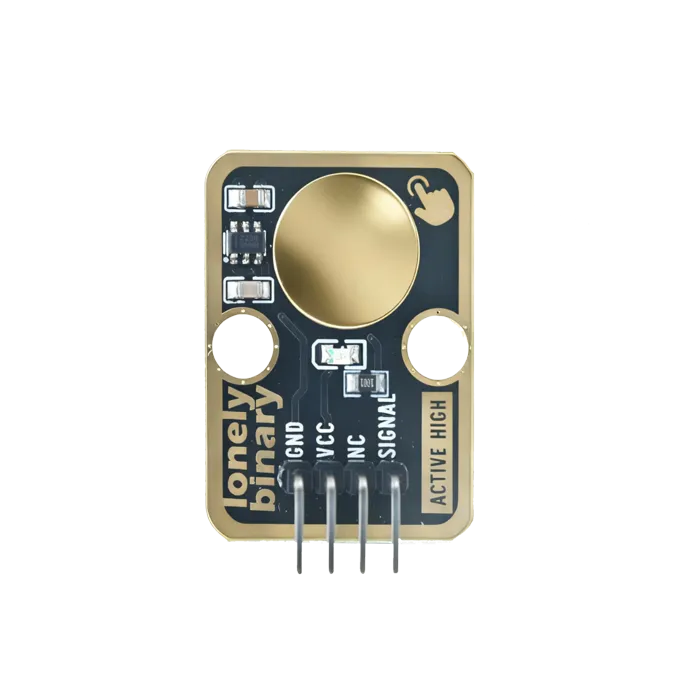
TP223 Touch Sensor
A capacitive pad that behaves like a button and works through a plastic panel — no hole, no moving part, nothing to wear out. This board is wired active-high and momentary, and neither is selectable.