
Specifications
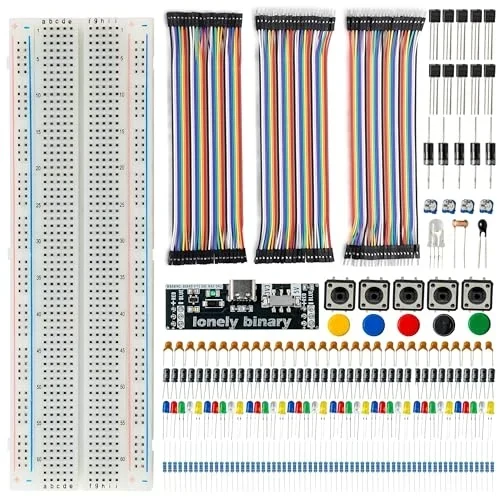
| Breadboard | 830 tie points, full size, two pairs of power rails |
|---|---|
| Power | A USB-C power module that plugs into the breadboard rails: 5 V or 3.3 V by switch. It is the standard breadboard power adapter, so its limits are that handbook's: half an amp in total, 200 mA on 3.3 V |
| Jumper wires | 120 Dupont wires, 20 cm: 40 male-to-male, 40 male-to-female, 40 female-to-female |
| Resistors | 100 Ω, 220 Ω, 1 kΩ, 4.7 kΩ, 10 kΩ and 1 MΩ |
| Capacitors | Ceramic 22 pF and 100 nF; electrolytic 10 µF and 100 µF |
| Light | LEDs in red, yellow, green, blue and white, 10 mm, and two RGB LEDs |
| Inputs | 12 × 12 mm push buttons with caps, potentiometers from 200 Ω to 1 MΩ, a light sensor and a temperature sensor |
| Semiconductors | 1N5819 Schottky diodes, S8050 NPN transistors and 2N7000 N-channel MOSFETs |
| Not in the box | A microcontroller, a battery, a multimeter and a USB-C cable. The circuits in this handbook need only the power module and a meter |
What it is
A breadboard, a power module for it, and a box of loose parts. There is nothing in it that runs a program: the first circuits here are an LED, a resistor and a button, and the later ones add a transistor. Each one is built in a few minutes and checked with a multimeter, so the reader learns what the circuit does by measuring it.
Where to start
The first chapter, The box, says what each kind of part is for and how to read the markings printed on it. The second sets up the bench: the breadboard, the power module and the multimeter. The circuits start at Light an LED.
The power module
The module in the box is the standard breadboard power adapter. It has its own handbook, which explains the fuse, the diode and why the 5 V rail reads about 4.7 V. This handbook says only what the experiments need.
When it doesn’t work
- How many of each part is in the box?
- The store listing gives the counts, and the box is the authority: the handbook never counts, because a box that has been used for a month has fewer. Every experiment says what kind of part it needs and how many, never more than a few.
- Does it come with a microcontroller?
- No. Everything here is a circuit powered from the power module, and every experiment ends by measuring it with a multimeter. The parts also work with any 3.3 V or 5 V board, including Arduino-compatible and ESP32 boards.
- Do I need a multimeter?
- Yes, for the way this handbook is written. The meter is how you check a resistor whose bands you cannot read, how you find out which pin of a transistor is which, and how you know a circuit works when an LED is too dim to judge.
- What is the power module?
- The standard Lonely Binary breadboard power adapter. It plugs into the breadboard rails, takes power from USB-C and gives 5 V or 3.3 V by slide switch. Its handbook explains which way round it goes and why the 5 V rail reads about 4.7 V.
- I lost the label on a part. How do I tell what it is?
- With the meter: resistance tells a resistor from a potentiometer, diode mode shows an LED or a diode and which way it points, and three legs in a small black body is a transistor or a MOSFET, which the meter can also tell apart. The handbook has a page for exactly this.
- The LEDs have no resistors. Will they burn out?
- They will if you connect one straight across the supply. An LED needs a resistor in series with it, and the first experiment is about choosing one.