Fundamentals
Soldering, breadboards, multimeters, pull-up resistors and logic levels. The things every other tutorial assumes you already know.
ESP32-S3 PinPulse Shield pinout
Every hole on the Lonely Binary ESP32-S3 PinPulse Shield: 44 nets on a male pin and a female socket each, the LED on all 36 GPIOs, and what that LED costs the pin.
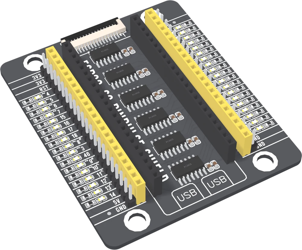
ESP32-S3 PinPulse Shield: an LED on All 36 GPIOs
The base for the Lonely Binary ESP32-S3: every GPIO on a male pin and a female socket with its own LED, six inverter chips so the lights cost your signals nothing, and a fifteen-way display port.
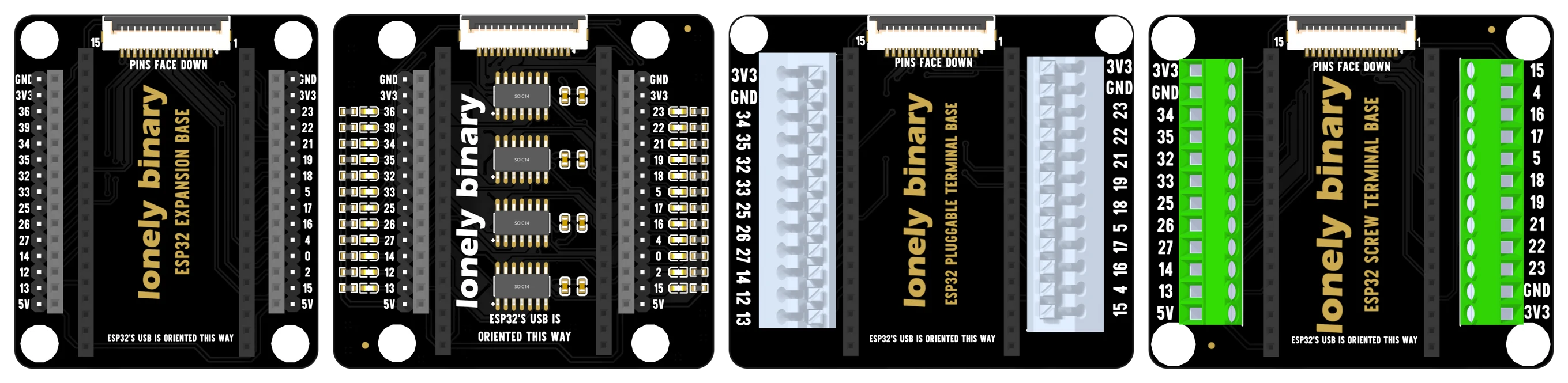
ESP32 Expansion Bases: 2.54 mm, PinPulse, Pluggable Terminal and Screw Terminal
Four bases for the 38-pin Lonely Binary ESP32. Which pins each one brings out, which way round the board goes, the fifteen-way display port they all share, and the twenty-four LEDs on the PinPulse.
Logic Level Converters: MOSFET 2/4/6-Channel, TXB0108 and TXS0108
Five boards that let a 3.3 V board and a 5 V part share a wire safely. Which one to use for I²C, SPI, serial or an LED strip, which side is which, and the three wires that come before any signal.
Logic Analyzer Kit, 8-Channel 24 MHz
Eight channels sampled at up to 24 MS/s, straight up a USB cable. It decodes I²C, UART and SPI at the speeds a microcontroller actually runs, and the sample rate is the number that decides the rest.
ESP32 Gold Edition pinout
All 38 holes on the Lonely Binary ESP32 Gold Edition — the four that can only ever be inputs, the five sampled at reset, and the six that are drilled, labelled and wired to nothing.
1. Arduino IDE Installation & Environment Setup
Complete download, installation, and basic setup of Arduino IDE on Windows for programming with the TinkerBlock kit.
29. ADC Concept
Learn ADC (Analog-to-Digital Conversion); outcome: serial prints A0 analog value (0–1023) and D2 digital value (0 or 1) together so you see continuous vs discrete, multi-level vs two-level.
45. Final Project: Free Integration
Final project: combine what you learned into one project; outcome: choose a theme (e.g. smart lamp, temp/humidity alarm, remote LED), finish wiring, code, and test—wrap up the course.
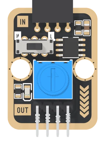
Analog to Digital Signal
An LM393 comparator on a TinkerBlock board: plug an analog block into the IN socket, set a threshold with the blue knob, and DIG tells your board whether the block's voltage is above or below it. The block's own voltage passes through on ANA, and a slide switch printed H and L turns the answer over.
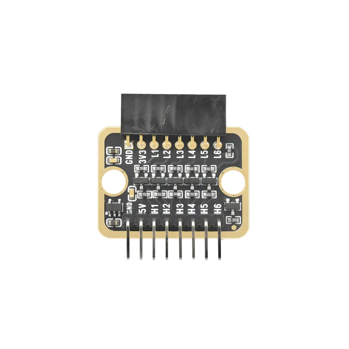
Logic Level Converter
Bidirectional 5 V to 3.3 V translation. The part that stops a 5 V sensor from quietly damaging a 3.3 V board.
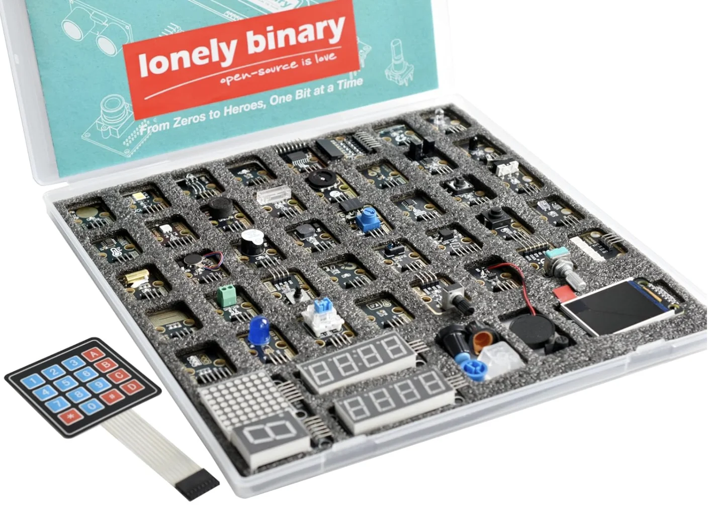
TinkerBlock
Our own modular series — sensors, displays and actuators that share one pin convention, one numbering scheme, and one set of wiring habits.
TinkerBlock 46-Piece Sensor Module Kit
Forty-four modules on gold-plated breakouts, sharing one pin convention — and the forty-five-lesson workshop written around them.
ESP32-S3 pinout
All 44 holes on the Lonely Binary ESP32-S3, what each one can do, and the twelve that are already spoken for before you wire anything.
Flash the board
Get Blink onto the board, and learn what to do when the upload fails — which the first time, it usually does.
Install the toolchain
Arduino IDE or PlatformIO, the ESP32 board package, and the USB driver your laptop is probably missing.