Specifications
| Input | 5 V from USB-C, through a 0.5 A resettable fuse and an SS24 Schottky diode, the same on all three boards. Both CC lines have 5.1 kΩ to GND, so a USB-C charger switches its 5 V on. The socket is power only: no data contacts |
|---|---|
| Current | 0.5 A in total from USB, shared by both sides: the fuse (Jinrui JK-nSMD050) holds 0.5 A and trips by 1.0 A, then resets itself once the fault is gone and it has cooled |
| Standard output | 5 V or 3.3 V, one slide switch per side. 5 V is the USB supply after the diode, about 4.5 to 4.9 V under ordinary loads. 3.3 V comes from one XC6206 rated for 200 mA, shared by both sides. A red LED shows 5 V, a blue LED 3.3 V |
| Step-down output | 1.25 V to about 3.5 V per side, set with a 2 kΩ trimmer: 2 × AMS1117-ADJ linear regulators with 220 Ω from OUT to ADJ. The back prints 1V2-3V8; 3.8 V needs light load and a charger at the top of the USB range |
| Booster output | From about 4.3 V (its input less a diode) up to 28 V per side, set with a 200 kΩ trimmer: 2 × MT3608 boost converters at 1.2 MHz. The trimmer is ± 25 %, so the top of the knob can pass 28 V. About 160 mA at 12 V, both sides together |
| Pins | Two blocks of 2 × 3 male pins, soldered, pointing down: three + and three − at each end. Both ends print + − left to right, so the adapter fits a breadboard one way round |
| Board | 53.34 × 16.36 mm, 1.6 mm thick, black with gold (ENIG) pads. Pins reach 7.90 mm below the board |
| Revision | Standard V5, step-down V4, booster V0 (its model files are released as v1.0). Every board prints its revision on the back |
What it does
A breadboard has two pairs of power rails, one down each long edge, and nothing in them. These adapters sit across one end of the breadboard with a block of pins in each pair, take 5 V from a USB-C charger, and put a voltage on both sides at once. Each side is set on its own; the − rails are one ground.
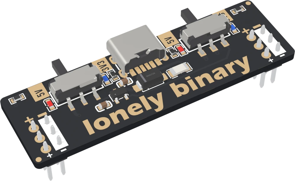
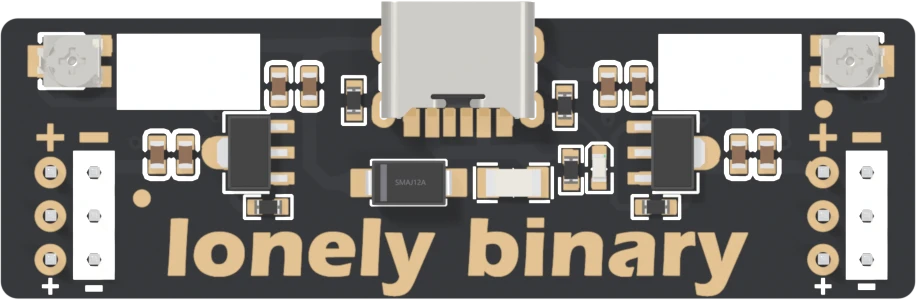
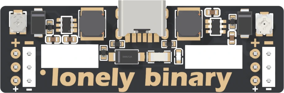
Three boards
| Makes | How | Limit that matters | |
|---|---|---|---|
| Standard | 5 V or 3.3 V per side | USB after a diode; an XC6206 for 3.3 V | 3.3 V is 200 mA, shared |
| Step-down | 1.25 to about 3.5 V per side | Two AMS1117-ADJ linear regulators | Heat at hundreds of mA |
| Booster | About 4.3 to 28 V per side | Two MT3608 boost converters | About 160 mA at 12 V |
All three put the same half-amp resettable fuse and the same Schottky diode between the socket and everything else, so half an amp in is the ceiling on every board.
Wiring, in four lines
- Seat the adapter across one end of the breadboard, pins in both pairs of rails, each + over a rail the breadboard marks +.
- On the standard, slide each side to 5V or 3V3 and check the LED. On the others, set each side's voltage with a meter before wiring anything.
- Plug in a USB-C charger or a computer port.
- Wire parts from the rails, and keep the total under half an amp.
Where to start
The handbook below is twelve short articles. Read Which way round it goes before the first cable goes in: it is the one thing on these boards that can damage a part. Then the chapter for your board — the standard's three articles, the step-down's two or the booster's two.
When it doesn’t work
- Why does the 5 V rail read 4.7 V?
- Because it is the USB supply after a fuse and a diode, and each takes a little. The diode takes about 0.2 to 0.4 V depending on the current, the fuse up to a few tenths more near half an amp, so a 5 V rail normally reads about 4.5 to 4.9 V. That is inside what 5 V parts are built for; most accept 4.5 to 5.5 V.
- Which way round does it go?
- The way that puts each + pin on a rail the breadboard marks +. Both ends print + − left to right, so on most breadboards one way round is right for both sides and the other is backwards for both. On a breadboard whose rails are printed mirror-image, one side is backwards whichever way round you turn it: use the other side, or re-mark it.
- Can I power an ESP32 from the 3.3 V side?
- Not with Wi-Fi on. The 3.3 V comes from a regulator rated for 200 mA, shared by both sides, and Wi-Fi bursts pull well over 300 mA. Set a side to 5V and wire it to the dev board's 5V or VIN pin instead, so its own regulator makes the 3.3 V.
- How much current can I take?
- Half an amp in total from the USB-C input, whichever board and whichever side: that is what the fuse holds. The standard's 3.3 V is further limited to 200 mA. The step-down gets hot well before half an amp at low voltages, and the booster trades current for voltage — about 160 mA at 12 V.
- The step-down says MAX 1A and the booster MAX 2A on the back. Are those wrong?
- They are the regulator chips' own ratings, not what these boards can deliver. Every milliamp comes in through a fuse that holds 0.5 A, so neither board can supply 1 A or 2 A for more than a moment.
- What happens if I short the rail?
- The fuse heats and trips within seconds, and the rail drops to nearly zero. Nothing is damaged and nothing needs replacing: take the short away, wait a minute for the fuse to cool, and the rail comes back.
- Are breadboards included?
- No. The adapters plug into a standard 400-point or 830-point solderless breadboard, sold separately.