The first number
Five wires, one library and about fifteen lines. The part worth understanding is not the counting — it is the four register writes before it, because a MAX7219 wakes up switched off and scanning one digit out of eight, and nothing warns you about either.
Four writes before anything
shutdown(0, false) has run, and no library does it for you.Press Run setup() and watch the three register rows before the digits start filling. Two of them are the reason a first attempt shows nothing.
A MAX7219 comes out of power-up in shutdown mode, with the scan oscillator stopped and every segment off. That is deliberate: the digit registers hold whatever random bytes were in the RAM at power-up, and blanking is how the chip avoids putting them on your display. It also comes up with the scan limit at its minimum, which means one digit out of eight.
Neither is an error condition and neither produces a warning. A sketch that forgets the first gets a dark display; a sketch that forgets the second gets one digit.
LedControl's constructor handles the scan limit for you — it sets it from the
device count you pass in — which is why the omission mostly bites people writing
the registers by hand. The shutdown register it leaves to you, every time.
The sketch
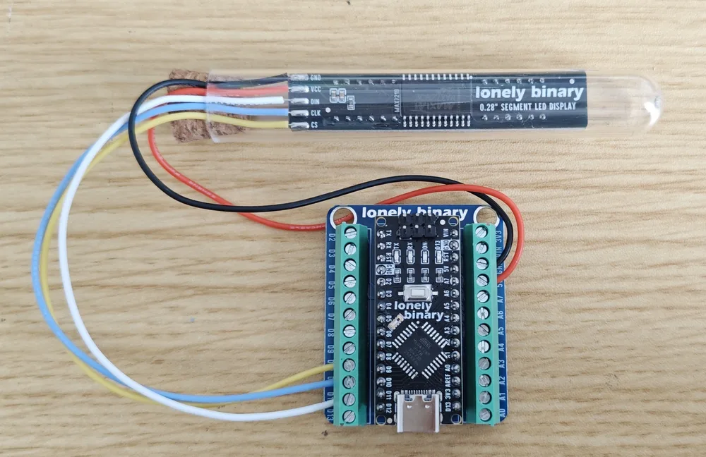
Wire five leads: GND to GND, VCC to 5 V and not to 3V3, then DIN, CLK and CS to any three digital pins. The example uses D12, D11 and D10 because that is what the sketches in the Segment-Display repository use, but there is nothing special about them — this is bit-banged, not hardware SPI.
What setDigit is doing
lc.setDigit(0, pos, value, point) is four things at once, and it is worth
unpicking because the rest of the book is about the parts of it you cannot reach
this way.
- The first
0is which chip in the chain, not which digit. posis the digit, 0 to 7, counting from the left.valuegoes to the chip's own code B decoder, which knows 0 to 9 and a handful of letters and nothing else.pointsets bit 7, which is the decimal point — or, on a colon panel, the colon.
So setDigit is the easy path and it comes with a font you did not choose.
Getting arbitrary shapes onto the display means turning the decoder off, which
is two chapters away.
Why loop() is empty
Because it can be. Everything the display is showing is eight bytes in the chip's memory, and the chip refreshes it at around 800 Hz using its own oscillator.
Unplug your board's serial monitor, add a delay(10000) to loop(), put the
sketch into a busy Wi-Fi connection — the time stays on the display throughout.
That is the whole benefit of a driver chip over multiplexing in software, and
this sketch is the smallest possible demonstration of it.
The code
Fills the eight digits left to right with 0 to 7, holds it, then shows 08:30 17:45 with both colons. Runs unchanged on an Uno; change the three pin numbers for anything else.
// First light: eight 0.28-inch digits on a MAX7219 driver board.
//
// Wiring, driver board to Arduino Uno:
//   GND -> GND
//   VCC -> 5V        (4.0 to 5.5 V; not the 3V3 pin)
//   DIN -> D12
//   CLK -> D11
//   CS  -> D10
//
// Arduino IDE: board "Arduino Uno", and the "LedControl" library by
// Eberhard Fahle from Sketch > Include Library > Manage Libraries.
// Nothing else to set.

#include <LedControl.h>

const int DIN_PIN = 12;
const int CLK_PIN = 11;
const int CS_PIN  = 10;

// The last argument is how many MAX7219 chips are chained. One board, one chip.
LedControl lc = LedControl(DIN_PIN, CLK_PIN, CS_PIN, 1);

void setup() {
  // The chip powers up in shutdown mode with its display blanked.
  lc.shutdown(0, false);      // false = not shut down = on

  // It also powers up scanning one digit. LedControl's constructor sets the
  // scan limit from the device count, so this is belt and braces - but it is
  // the line people leave out when they write the registers by hand.
  lc.setScanLimit(0, 7);      // digits 0 through 7

  lc.setIntensity(0, 8);      // 0 dimmest, 15 brightest
  lc.clearDisplay(0);

  // Fill the digits left to right. Position 0 is the leftmost digit.
  for (int pos = 0; pos < 8; pos++) {
    lc.setDigit(0, pos, (byte)pos, false);   // last argument is the point
    delay(180);
  }
  delay(800);
  lc.clearDisplay(0);
  delay(200);

  // 08:30 on the left panel, 17:45 on the right. On colon panels the point
  // of digit 1 is the left colon and the point of digit 5 is the right one.
  lc.setDigit(0, 0, 0, false);
  lc.setDigit(0, 1, 8, true);    // left colon
  lc.setDigit(0, 2, 3, false);
  lc.setDigit(0, 3, 0, false);
  lc.setDigit(0, 4, 1, false);
  lc.setDigit(0, 5, 7, true);    // right colon
  lc.setDigit(0, 6, 4, false);
  lc.setDigit(0, 7, 5, false);
}

void loop() {
  // Nothing. The chip holds the eight bytes and refreshes the display itself,
  // so the time above stays lit with the sketch doing absolutely no work.
}
Everything happens in setup() and loop() does nothing, which is the point being made: the display keeps showing the last thing it was sent because the chip is scanning it, not the sketch. Comment out the shutdown() line and upload again — the display stays dark and the compiler says nothing.
When it does not work
Almost always the shutdown register. A MAX7219 comes out of power-up blanked, deliberately, so that whatever was left in its RAM does not appear on the display. Without lc.shutdown(0, false) nothing you write ever shows, and there is no error anywhere.
The scan-limit register is still at its power-up value of 0, which means scan one digit. LedControl sets it from the device count you pass the constructor, so if you see this you are either writing registers by hand or the constructor's last argument is wrong.
Search for LedControl as one word. The one you want is by Eberhard Fahle and the header is LedControl.h. There are several forks with similar names; the original works with this board and is what every example here uses.
It is doing what it is told. setDigit sends the value to the chip's code B decoder, which understands 0 to 9 and then a minus, E, H, L, P and a blank. Anything above 15 is masked to four bits. For letters, setChar; for arbitrary shapes, the decoder has to come off entirely.
Check which end of the board you are calling digit 0. On this board position 0 is the leftmost digit of the left panel as you look at the display side, which is what both panels and the library agree on. If yours is mirrored, the display is in the tube back to front.
What setDigit actually puts on the wire, and why the display never changes until CS goes high.
Sixteen bits, one register →Edit this page — content/books/max7219-tube-clock/the-first-number.mdx
Questions about this product
See what other owners have asked, and read their solutions.
MAX7219 Vintage Tube LED Clock Kit
Loading discussions…
Discuss this article
Ask about this page. The answer stays here, on the page it belongs to, for whoever hits the same wall next.