Specifications
| Type | Eight-digit 0.28-inch seven-segment LED display with a MAX7219 driver, in a glass tube |
|---|---|
| In the box | 3 displays built into tubes, 6 loose four-digit panels, 3 loose driver boards, 6 tubes with cork stoppers, 1 diffusion sheet, 2 forty-pin header strips and 30 jumper leads of 150 mm |
| Panels supplied | 6 loose: 2 red with decimal points, 2 red with a colon, 2 blue with decimal points. There is no blue colon panel |
| How a display is made | One driver board takes two four-digit panels, one each side of the chip, and drives them as digits 0–3 and digits 4–7 |
| Driver chip | MAX7219CWG in a 24-pin wide SO: 8 digits by 8 segments, code B decoder, 16 brightness steps and its own scan oscillator |
| Wires to your board | 5 — GND, VCC, and the 3 signal wires DIN, CLK and CS |
| Protocol | 16-bit frames, most significant bit first, latched on the rising edge of CS. Up to 10 MHz, and no minimum speed |
| Supply voltage | 4.0 to 5.5 V, and 6 V is the absolute maximum. Not 3.3 V — the datasheet does not specify the part below 4.0 V |
| Logic threshold | 3.5 V minimum for a HIGH on DIN, CLK and CS, and it is a fixed voltage rather than a fraction of the supply. A 3.3 V board is below it |
| Supply current | 330 mA typical with every segment lit at full brightness; about 150 µA in shutdown |
| Brightness | 16 steps in software, from 1/32 to 31/32 duty. The peak is fixed by the 10 kΩ resistor on the board and cannot be raised from a sketch |
| Scan rate | About 800 Hz with all 8 digits scanned, from the chip's own oscillator |
| Digit height | 0.28 inch, which is 7.1 mm |
What it does
Eight seven-segment digits, driven by one chip, over three wires. The MAX7219 holds the eight bytes in its own memory and refreshes the display from its own oscillator at about 800 scans a second — so a number you send once stays lit while your sketch reads a sensor, joins Wi-Fi, or blocks for a second.
That is the whole reason to use a driver chip rather than wiring the digits directly. Eight digits is sixty-four LEDs; multiplexing them in software is sixteen pins and a refresh loop that can never stop.
What is in the box
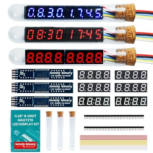
Three of the six displays arrive finished in their tubes: one red with decimal points, one blue with decimal points, one red with colons. The rest of the box is three driver boards, six loose panels and three empty tubes — which is exactly enough to make three more.
Two panels make one display
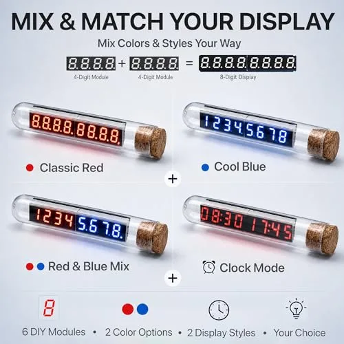
The driver board has a twelve-pad footprint either side of the chip, and each takes an ordinary four-digit 0.28-inch panel. The left one becomes digits 0 to 3 and the right one digits 4 to 7. Nothing in the wiring or the software knows which panel is which, so red beside blue works, and a colon panel beside a decimal one gives you a clock and a readout on one display.
Which panel
| You are showing | The panel | Why |
|---|---|---|
| A time, a timer, minutes and seconds | Colon | The colon is the only separator that reads as a time |
| A voltage, a temperature, a weight | Decimal points | 4.98 needs a point, and a colon cannot be one |
| A counter, a score, a raw number | Either | Neither separator gets used |
The colon is not a separate LED with its own pin. Each clock panel wires it to the decimal-point line of its second digit, so on the assembled eight the colons are digits 1 and 5 — and on the other six digits the point bit lights nothing at all. Eight segment lines, and the eighth is either the points or the colon. Never both.
Wiring, in five lines
- GND to your board's GND.
- VCC to 5 V — the 5V pin on an Uno, VIN on an ESP32, VBUS on a Pico. Not the 3.3 V pin.
- DIN to any digital pin — D12 on an Uno, GPIO 23 on an ESP32.
- CLK to any other — D11, or GPIO 18.
- CS to a third — D10, or GPIO 5.

VCC is the one that is not a free choice. The chip is specified from 4.0 V, and the 3.3 V pin on an ESP32 or a Pico is a regulator output that cannot supply the few hundred milliamps a lit display wants in any case.
Soldering
The three loose driver boards need their two panels and their five-pin header fitted. That is twenty-nine through-hole joints per display on 2.54 mm pitch, which is about as forgiving as soldering gets — but it is not optional.
A wire pushed through an unsoldered hole makes a connection whose resistance changes every time anything moves, and what you get is missing digits, segments lighting at random, or a display that works until you nudge the desk. All three read like a wiring mistake or a library problem, and people spend the evening in the sketch.
Where to start
The handbook below runs from why eight digits need a driver chip through to a clock that sets itself over Wi-Fi. If you only read two of them, read Five volts, and the threshold before you wire anything and The first number to get it lit.
Example
Install LedControl by Eberhard Fahle from the Arduino Library Manager — the
header is LedControl.h.
// Eight digits on a MAX7219: GND->GND, VCC->5V, DIN->D12, CLK->D11, CS->D10
#include <LedControl.h>

LedControl lc = LedControl(12, 11, 10, 1);   // DIN, CLK, CS, one chip

void setup() {
  lc.shutdown(0, false);     // it powers up blanked
  lc.setScanLimit(0, 7);     // all eight digits
  lc.setIntensity(0, 8);     // 0 dimmest, 15 brightest
  lc.clearDisplay(0);

  // 08:30 17:45. On colon panels the point of digit 1 is the left colon
  // and the point of digit 5 is the right one.
  lc.setDigit(0, 0, 0, false);
  lc.setDigit(0, 1, 8, true);
  lc.setDigit(0, 2, 3, false);
  lc.setDigit(0, 3, 0, false);
  lc.setDigit(0, 4, 1, false);
  lc.setDigit(0, 5, 7, true);
  lc.setDigit(0, 6, 4, false);
  lc.setDigit(0, 7, 5, false);
}

void loop() {
  // Nothing. The chip holds the bytes and refreshes the display itself.
}
When it doesn’t work
- The listing says 3.3 V or 5 V. Which is it?
- Power it from 5 V. Maxim's datasheet gives the operating supply as 4.0 to 5.5 V, so 3.3 V is below the range the part is specified in. A 3.3 V board can usually still drive the three signal lines — the guaranteed HIGH threshold is 3.5 V and a typical part switches well under that — but there is no margin in it. For anything permanent, put a level converter in DIN, CLK and CS.
- Nothing lights and the sketch uploaded fine.
- A MAX7219 comes out of power-up in shutdown with the display blanked, deliberately, so that whatever was in its RAM does not appear. Without shutdown(0, false) nothing you write ever shows and nothing warns you. If that call is there, write 1 to the display-test register instead: it overrides shutdown and every digit byte, so if all sixty-four LEDs light your wiring is fine.
- Only one digit lights.
- The scan-limit register is at its power-up value of 0, which means scan one digit. Set it to 7 for all eight. LedControl's constructor sets it from the device count you pass in, so this mostly happens to people writing the registers by hand.
- The colon will not light.
- There is no colon register. Each clock panel wires its colon to the decimal-point line of its second digit, so on the assembled eight they are digits 1 and 5 — bit 7 on any other digit lights nothing at all. And a decimal-point panel has no colon to light, whatever you send it.
- My glyphs come out mirrored.
- A segment table written for the wrong bit order. The MAX7219 puts the decimal point at bit 7 and then counts down: A at bit 6, B at 5, G at bit 0. TM1637 and 74HC595 tables count up from A at bit 0, so asymmetric characters come out reflected. Symmetric ones — 0, 1, 8 — look perfect, which is what makes it hard to spot.
- Can I make it brighter than setIntensity(0, 15)?
- Not without changing a resistor. The peak segment current is set by RSET, the single 10 kΩ chip resistor on the back of the driver board, and it already puts the segments near the chip's 40 mA maximum. The intensity register only ever scales that down. The diffusion sheet also costs light — take it off if you want the digits at their sharpest.
- Can I chain two displays on the same three wires?
- Not on this board. Chaining MAX7219s means wiring one chip's DOUT to the next one's DIN, and these boards do not bring DOUT out to a pad. Two displays share GND, VCC, DIN and CLK and take a CS pin each, which is one extra pin per display and simpler to reason about anyway.
- Does it have to go in the tube?
- No. The tube, the cork and the diffusion sheet are cosmetic and the display works identically on a desk. The tube is a friction fit both ways, so a finished display goes in and comes back out.