What is in the box
Three displays arrive finished in their tubes. Three more arrive as a driver board and two four-digit panels each, and which two panels you choose is the only real decision in the kit — it fixes the colour and whether the result can show a time.
What is actually in there
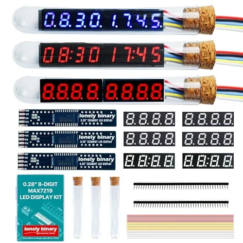
Counting it: three finished displays in tubes, six loose four-digit panels, three loose driver boards, six tubes and corks in total, one diffusion sheet, two forty-pin header strips and thirty 150 mm jumper leads.
The arithmetic is the point. Three loose driver boards take two panels each, and six loose panels is exactly enough — so the box makes six finished displays and gives you six tubes to put them in.
Two panels make one display
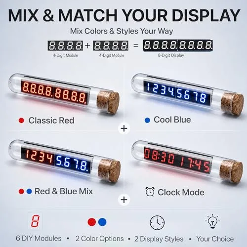
Each panel is a standard four-digit 0.28-inch module with twelve pins. It drops into one of the two footprints on the driver board, and the chip in the middle drives the left one as digits 0 to 3 and the right one as digits 4 to 7. Nothing in the wiring or the software knows or cares which panel is on which side.
Try the combinations. Three of the four exist in the box; the fourth does not, and it is worth knowing which before you commit two panels to a board.
Colon or decimal point
That is the whole difference between the two panel styles, and it decides what the display is good for.
| The panel has | Good for | Because |
|---|---|---|
| A colon between the middle digits | Times, timers, anything NN:NN | A colon is the only separator that reads as a time |
| A decimal point under every digit | Voltages, temperatures, weights | 4.98 needs a point, and a colon cannot be one |
They are the same twelve pins in the same order, and the same eight segment lines. What changed is where the eighth one goes on the panel — which is a fact with more consequences than it sounds like, and is a chapter of its own.
The tube and the sheet
The glass tube and the cork are the cosmetic half of the kit and they are not load-bearing: the display works on a desk exactly as well. The diffusion sheet is not cosmetic in the same way, though — it is a single square of dark film that sits over the digits and softens them from eight sharp LEDs into something that reads like a glow.
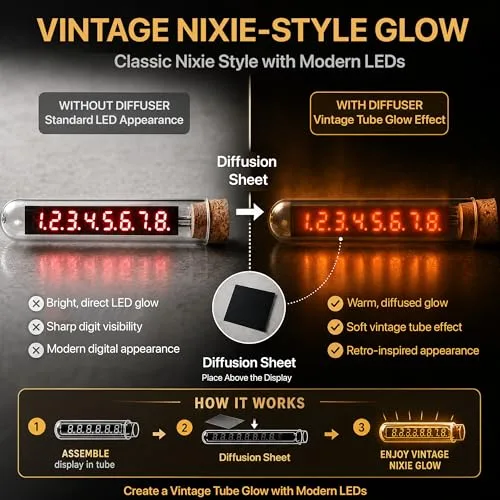
There is one sheet for six possible displays. It goes to whichever one you put somewhere people look at.
When it does not work
Three are already occupied: a red display with decimal points, a blue one with decimal points, and a red one with colons. The other three tubes are empty and are for whatever you build from the six loose panels and three loose driver boards.
The six loose panels are two red with decimal points, two red with a colon and two blue with decimal points. There is no blue colon panel in this box, so a blue display can show numbers but not a time with a separator. The blue-and-red mixed build is the usual workaround: colons on the red half.
No. The two twelve-pad footprints are identical and the chip drives them as digits 0 to 3 and digits 4 to 7 without knowing what is fitted. Red beside blue works, and a colon panel beside a decimal one gives you a clock on the left and a reading on the right.
Each display needs five pins and the strips are forty pins each, so eighty pins covers sixteen displays. Snap five off; the strip is scored between every pin. The three pre-built displays already have theirs fitted with the ribbon cable soldered on.
The five-pin header arrives loose, and a display that has been pressed together instead of soldered fails in ways that look like software faults.
Solder it before you plug it →Edit this page — content/books/max7219-tube-clock/whats-in-the-box.mdx
Questions about this product
See what other owners have asked, and read their solutions.
MAX7219 Vintage Tube LED Clock Kit
Loading discussions…
Discuss this article
Ask about this page. The answer stays here, on the page it belongs to, for whoever hits the same wall next.