
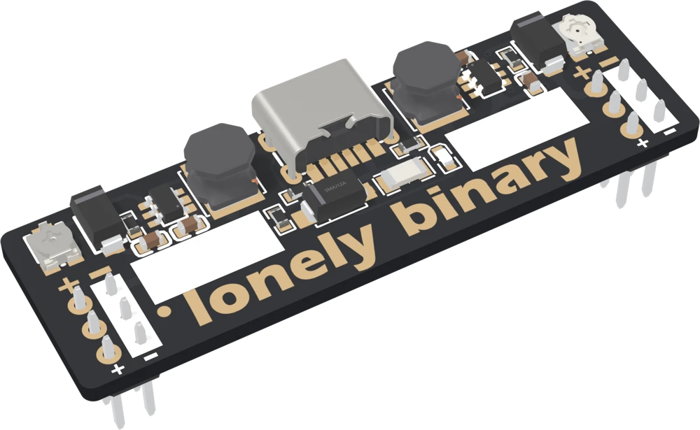
Same plug, different voltage
All three fit the breadboard the same way and share one half-amp fuse. Pick by the voltage your circuit needs.
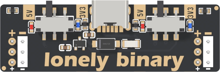 See this board 5 / 3.3V, by switchBreadboard Power Adapter, Standard 5 V / 3.3 V, 3-Pack3.3 V budget: 200 mA, shared
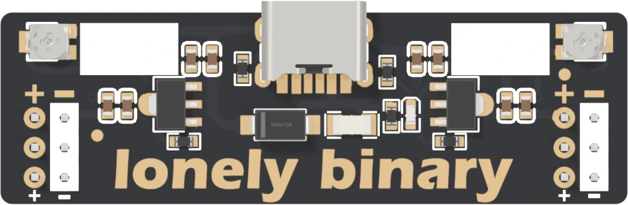 See this board 1.25–3.5V, by trimmerBreadboard Power Adapter, Step-Down 1.25–3.5 VRegulators: 2 × AMS1117-ADJ
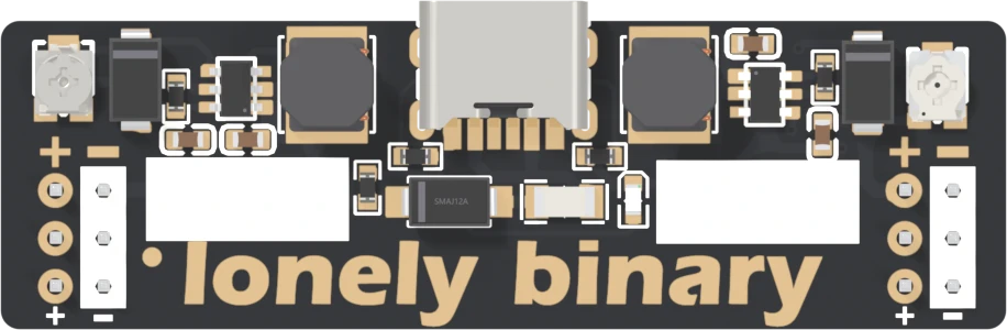 You have this4.3–28V, by trimmerBreadboard Power Adapter, Booster up to 28 VAt 12 V: 160 mA, both sides
The whole handbook12 articles · 55 minQuick referencePDF · 415 KBDatasheetPDF · olimex.comModel (GLB)GLB · 3.2 MBCAD (STEP)ZIP · 2.7 MBDrawing (PDF)PDF · 1.4 MBDrawing (DXF)ZIP · 121 KBPinout and specsThe pin table, and the questions people ask first
Community
Ask a question ↗Product questions
See what other owners have asked, and read their solutions.
Breadboard Power Adapter, Booster up to 28 V
Loading discussions…
Need another
Not on general sale yet. Reply to your order and we will sort out a spare — quote bbpwdbt.
Order or missing parts?
Email us or reply to your order, and quote bbpwdbt — that identifies the product. If something is missing from the bag, your order is the record of what shipped.
Take it with you
Point a phone camera at the code and this page opens there. It is the same address as the one printed on your box, so it is also what to show someone you are passing the board to.