This lesson uses: Arduino UNO R3 board, TinkerBlock TK09 Voltmeter module, jumper wires (or breadboard). Use analog input to measure voltage and convert to real value; outcome: serial shows voltage (V); with the module’s divider you can display about 0–25V.
1. Wiring
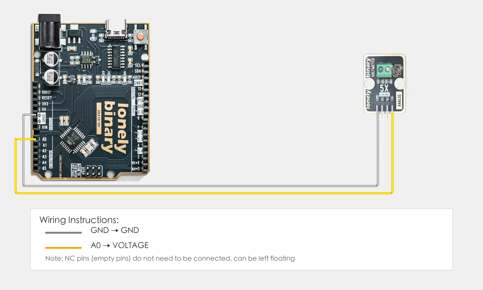
Connect TK09 Voltmeter to Arduino:
- GND → Arduino GND
- SIG → Arduino A0
- NC leave unconnected
2. New sketch
- Arduino IDE: File → New (or Ctrl/Cmd + N) to create a blank sketch
- Confirm board and port are selected (same as Lesson 01)
- Type the code below into the default
setup()andloop()yourself
3. Program structure
Same as last lesson: two fixed blocks setup() and loop().
setup(): Start serial; runs once.loop(): Keep repeating “read analog → convert to voltage → print to serial → wait → repeat”.
Pin voltage times the divider ratio gives actual voltage; serial will show volts.
4. Code to write
Type the code below into setup() and loop() (do not copy-paste; typing it yourself helps you remember):
// Voltage measurement: A0 reads divided voltage; multiply by ratio for actual (e.g. 0-25V)
#define VOLTAGE_PIN A0
const float DIVIDER_RATIO = 5.0;   // Divider ratio to match module (e.g. 5:1 => actual = read × 5)

void setup() {
  Serial.begin(9600);
  Serial.println("Voltmeter program started");
}

void loop() {
  int val = analogRead(VOLTAGE_PIN);   // A0, 0-1023
  float voltage = val * (5.0 / 1023.0);        // Pin voltage 0-5V
  float actualVoltage = voltage * DIVIDER_RATIO;   // Actual measured voltage
  Serial.print("Voltage: ");
  Serial.print(actualVoltage, 2);
  Serial.println("V");
  delay(500);   // Update every 0.5 s
}
Program notes
Overall idea: TK09 divides the measured voltage and feeds A0; Arduino sees 0–5V as 0–1023. Convert to pin voltage (0–5V), then multiply by divider ratio for actual voltage (e.g. 5:1 → 0–25V). Set DIVIDER_RATIO to match your module.
| Code | In this lesson |
|---|---|
val * (5.0 / 1023.0) | ADC → pin voltage (0–5V) |
voltage * DIVIDER_RATIO | Undo divider to get actual voltage; set ratio from module specs |
5. Hands-on
- After entering the code, click Verify (✓) to compile
- Click Upload (→) to upload to the board
- Open Serial Monitor (Tools → Serial Monitor, baud 9600)
- Watch serial: current voltage in V
- (Optional) Connect different voltage sources and observe the reading
Expected result:
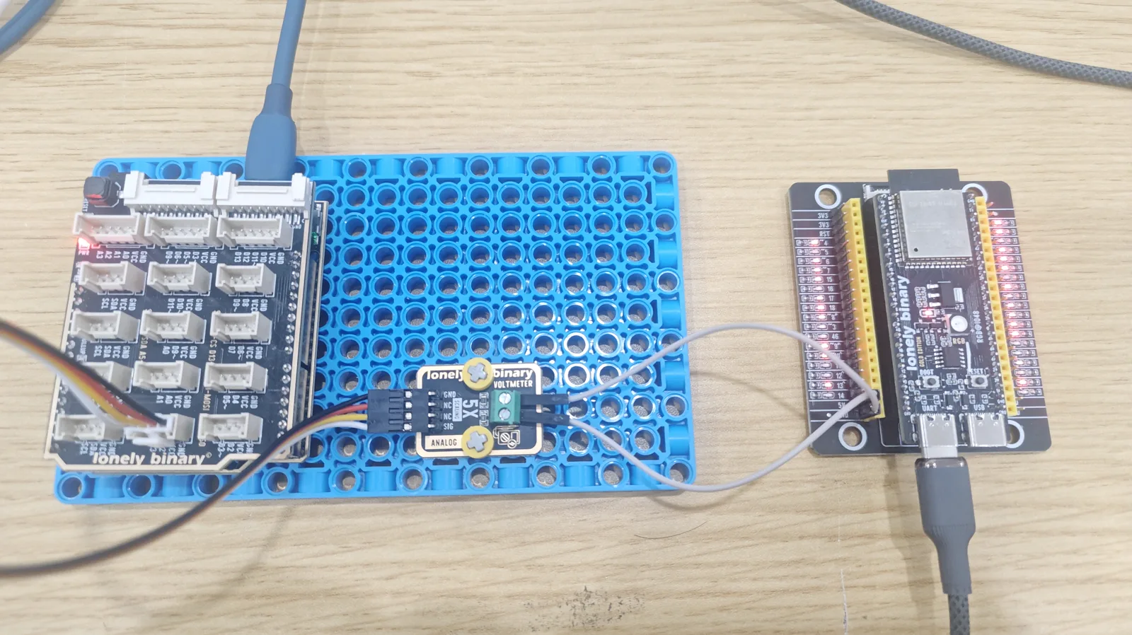
Serial monitor:
Voltmeter program started
Voltage: 5.00V
Voltage: 5.01V
Voltage: 4.95V
...
Note: TK70 Linear Hall Sensor is different (magnetic field); you can try it separately.
Proceed to Lesson 36.
Edit this page — content/guides/tinkerblock-workshop/35-voltmeter.mdx
Questions about this product
See what other owners have asked, and read their solutions.
Voltmeter
Loading discussions…
Discuss this article
Ask about this page. The answer stays here, on the page it belongs to, for whoever hits the same wall next.