Specifications
| Type | Resistive voltage divider, analog output. No active parts and no supply |
|---|---|
| Scaling | 5 to 1: SIG is exactly one fifth of the input. 30 kΩ over 7.5 kΩ, ±1 % parts going by their part numbers |
| Maximum input | 25 V on a 5 V board such as an Uno; about 15.5 V on an ESP32 or ESP32-S3; 16.5 V on a Pico. DC, positive, never mains |
| Input resistance | 37.5 kΩ across the terminal: it draws 0.24 mA from 9 V |
| Pins to wire | 2 of the 4: GND and SIG. The two NC pins are connected to nothing, and there is no VCC |
| Header | 4-pin right-angle male, 2.54 mm pitch: GND, NC, NC, SIG, with GND on the square pad |
| Terminal | 2-way screw terminal, 3.5 mm pitch (JILN JL102-35002G01). Left screw GND, right screw +, with the header at the bottom. 26–16 AWG, strip 4–5 mm. The terminal's own rating is 300 V 10 A; that is not the block's range |
| Board | 22.4 × 30.4 mm, two 4.8 mm mounting holes 16 mm apart |
| In the box | 1 × TK09 block. It also ships inside the TinkerBlock kits |
What it is
Two resistors and a screw terminal. The voltage you want to measure goes on the terminal, across a 30 kΩ resistor and a 7.5 kΩ resistor in series, and SIG is the point between them. The bottom resistor is a fifth of the total, so SIG is exactly a fifth of the input. Your board reads SIG on an analog pin and multiplies by five.
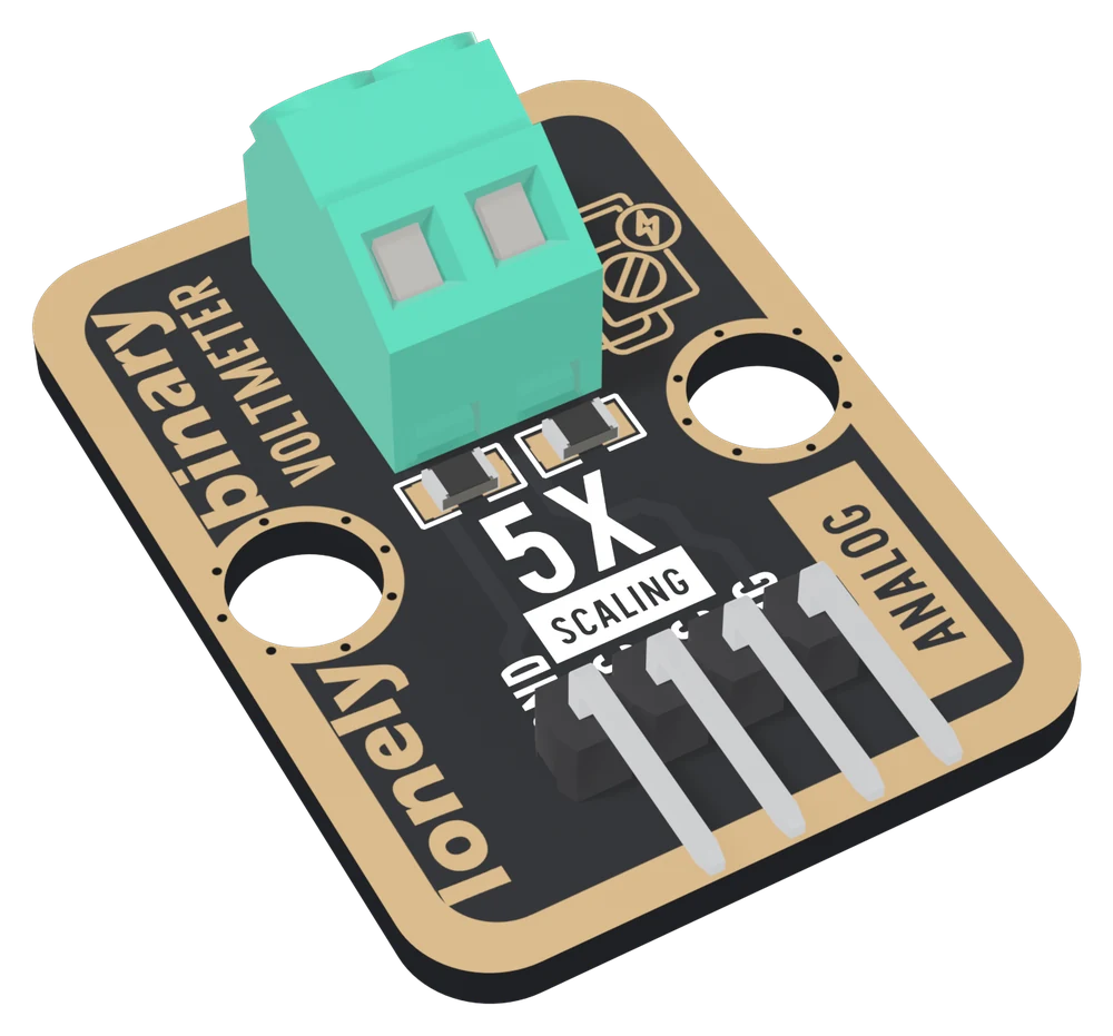
There is no supply pin and nothing to power. There is also no protection: the divider divides whatever it is given, so the limit is set by your board.
| Your board | SIG to | Reads up to | Most on the terminal |
|---|---|---|---|
| Arduino Uno | A0 | 5 V | 25 V |
| ESP32 | GPIO 34 | about 3.1 V | about 15.5 V |
| ESP32-S3 | GPIO 4 | about 3.1 V | about 15.5 V |
| Raspberry Pi Pico | GP26 | 3.3 V | 16.5 V |
It measures from GND. The terminal's left screw is your board's GND, so the minus side of what you measure must go there, and a part whose ends are both above GND cannot be measured by clipping across it.
Which pin is which
Terminal at the top, header at the bottom, reading left to right:
| GND | to your board's GND | the square pad: count from here |
| NC | nothing | not connected on the board |
| NC | nothing | not connected on the board |
| SIG | to an analog pin | a fifth of the input |
And the terminal, the same way up: left screw GND, right screw +. Nothing on the board prints either.
Wiring, in four lines
- GND to your board's GND.
- SIG to an analog pin: A0 on an Uno, GPIO 34 on an ESP32, GPIO 4 on an ESP32-S3, GP26 on a Pico. On the ESP32s these are ADC1 pins, which keep working while Wi-Fi is on.
- The minus of what you measure to the left screw.
- The plus, DC and under your board's limit, to the right screw.
Example
// The pin SIG is wired to. Uno: A0. ESP32: 34. ESP32-S3: 4. Pico: 26.
const int SIG_PIN = A0;

// Uno: 5.0 and 1023. Pico: 3.3 and 1023. The ESP32s do not use these.
const float VREF = 5.0;
const float ADC_MAX = 1023.0;

float sigVolts() {
#if defined(ARDUINO_ARCH_ESP32)
  return analogReadMilliVolts(SIG_PIN) / 1000.0;  // calibrated
#else
  return analogRead(SIG_PIN) * VREF / ADC_MAX;
#endif
}

void setup() {
  Serial.begin(115200);
}

void loop() {
  Serial.print(sigVolts() * 5.0, 2);  // the terminal is 5 x SIG
  Serial.println(" V");
  delay(500);
}from machine import ADC, Pin
import sys
import time
# The GPIO number SIG is wired to. ESP32: 34. ESP32-S3: 4. Pico: 26.
adc = ADC(Pin(34))
if sys.platform == "rp2":
def sig_volts():
return adc.read_u16() * 3.3 / 65535
else:
adc.atten(ADC.ATTN_11DB) # full range; the default is ~1 V
def sig_volts():
return adc.read_uv() / 1_000_000
while True:
print("{:.2f} V".format(sig_volts() * 5.0)) # the terminal is 5 x SIG
time.sleep(0.5)Where to start
The handbook below is twelve short articles, each with a working figure. The first reading is the whole build: four wires, a 9 V battery and a sketch that prints volts.
If you only read one, read it measures from GND. It is the reason a battery reads zero, and the reason not to clip the terminal across a part of a circuit.
And before anything above 15 V goes on the terminal, read how high you can go for your board.
When it doesn’t work
- Which screw is plus?
- With the terminal at the top and the header pins pointing down, the right screw is plus and the left screw is GND. Nothing on the board is marked. The GND screw is the same copper as the header's GND pin, which a multimeter's continuity beep confirms in a second.
- Where does VCC go?
- Nowhere: the block has no VCC. It is two resistors, and the voltage you measure drives them. The two middle header pins are NC. The voltage to measure goes on the screw terminal, not the header.
- How high can I measure?
- Five times what your board's analog pin reads. 25 V on an Uno, which is what the back of the board says. About 15.5 V on an ESP32 or ESP32-S3, whose ADC stops at roughly 3.1 V. 16.5 V on a Pico. Above that the reading sits at its maximum and the pin is past its rating.
- My battery reads 0 V.
- The battery's minus is not on the GND screw. The block measures the + screw from your board's GND, so without the minus wire there is no loop and SIG sits at 0 V. Both wires go on the terminal.
- Can I measure across a resistor in my circuit?
- Only if its lower end is GND. The GND screw is your board's GND, so putting it anywhere else pulls that point to ground and can short part of the circuit. Measure each end from GND and subtract instead.
- The reading is a percent or two off my multimeter.
- Expected: the resistors' tolerance and your board's reference voltage. Divide the meter's reading by the sketch's and multiply every reading by that factor. It takes out every error that scales, whatever caused it.
- Can I measure mains or AC with it?
- No. AC puts a negative voltage on SIG every half cycle, and mains is never connected to this block or anything else with a header. The terminal's 300 V rating is the terminal's alone and says nothing about what the block can measure.