Specifications
| Type | Linear Hall effect sensor |
|---|---|
| Output | Analog, centred at half supply |
| Response | Voltage rises for one pole, falls for the other |
| Supply voltage | 3.3 V or 5 V |
What it is
Where TK18 gives you a yes or no, this gives you a number: the output sits at half the supply with no field and moves up or down depending on which pole is near and how strong it is.
That bipolar behaviour is the useful part. The direction of the swing tells you the polarity, so you can distinguish a north pole approaching from a south pole approaching — which a digital Hall switch cannot do.
The classic application is contactless current measurement: current through a conductor makes a field proportional to it, so a Hall sensor near the wire reads current without breaking the circuit. Dedicated parts like the ACS712 are this idea with the conductor built in and calibrated.
Because the resting output is half the supply, it inherits every ADC caveat: on an ESP32 keep it on ADC1, and expect the reading to shift if your supply does.
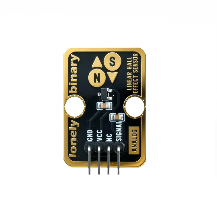
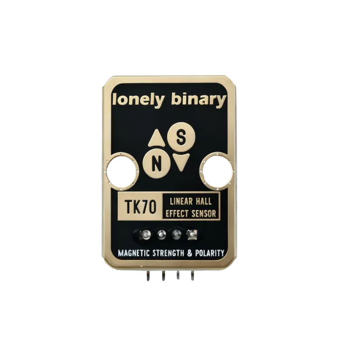
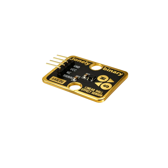
Pinout
- GND (negative): Like the negative terminal (-) of a battery, connect to the control board's GND
- VCC (positive): Like the positive terminal (+) of a battery, connect to the control board's 3.3V or 5V (this module supports both 3.3V and 5V)
- NC (no connection): No actual circuit connection, included for unified interface, can be left unconnected
- SIGNAL (signal output): Magnetic field strength output pin, connect to the control board's analog input pin (e.g. Arduino A0 or Pico GPIO 26)
- Stronger magnetic field results in higher output voltage
- Weaker magnetic field results in lower output voltage
- Can detect magnetic poles (N pole and S pole output different voltage values)
Wiring
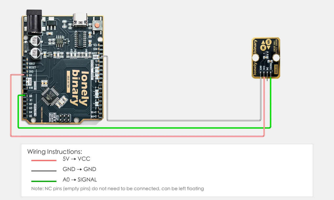
- GND → Control board GND
- VCC → Control board 3.3V or 5V
- SIGNAL → Control board analog input pin (use the pin defined in your program)
Example
// Pin number: change this to match your wiring
#define HALL_PIN A0  // Arduino analog input pin connected to SIGNAL (e.g. A0)

void setup() {
  // Initialize pin mode
  pinMode(HALL_PIN, INPUT);   // Set Hall sensor pin as input (to read analog value)

  // Start serial for debugging (9600 baud)
  Serial.begin(9600);

  Serial.println("Linear Hall sensor program started");
  Serial.println("Reading magnetic field strength value and output via serial");
}

void loop() {
  // Read Hall sensor analog value (0-1023)
  int sensorValue = analogRead(HALL_PIN);  // Read sensor pin analog value: 0=no magnetic field, 1023=strong magnetic field

  // Convert analog value to voltage value (0-5V)
  float voltage = sensorValue * (5.0 / 1023.0);

  // Output strength value
  Serial.print("Magnetic field strength: ");
  Serial.print(sensorValue);
  Serial.print(" | Voltage: ");
  Serial.print(voltage, 3);
  Serial.println("V");

  delay(100);  // Brief delay to avoid reading too fast
}# Import required modules
from machine import Pin, ADC # GPIO control and ADC
import time # For delay (time.sleep)
# Pin number: change this to match your wiring
HALL_PIN = 26 # GPIO connected to SIGNAL (e.g. GPIO 26, must be ADC pin)
# Create ADC object
hall = ADC(Pin(HALL_PIN)) # Set Hall sensor pin as ADC mode (to read analog signal)
print("Linear Hall sensor program started")
print("Reading magnetic field strength value and output via serial")
# Main loop: runs forever
while True:
# Read Hall sensor analog value (0-65535)
sensor_value = hall.read_u16() # Read sensor pin analog value: 0=no magnetic field, 65535=strong magnetic field
# Convert analog value to voltage value (0-3.3V)
voltage = sensor_value * (3.3 / 65535.0)
# Output strength value
print(f"Magnetic field strength: {sensor_value} | Voltage: {voltage:.3f}V")
# Delay 100 milliseconds to avoid reading too fast
time.sleep_ms(100)When it doesn’t work
- The output sits at half scale and will not go to zero.
- That is the no-field state and it is correct. Subtract the resting value to get the field.
- The value drifts when other things switch on.
- The output is ratiometric — it scales with the supply. A sagging rail moves the reading. Measure the supply too, or use a regulated one.
- It barely responds to a magnet.
- Linear Hall sensors are far less sensitive than digital ones. Get the magnet within a few millimetres, and use a neodymium one.