This lesson uses: Arduino UNO R3 board, TinkerBlock TK94 Five-Direction Joystick module, TinkerBlock TK01 XL LED module, jumper wires (or breadboard). Use analog input to read joystick direction; outcome: serial shows “Up / Left / Down / Right / Press / Center”; when you push a direction the LED is on, when you press or center the LED is off.
1. Wiring

2. New sketch
- Arduino IDE: File → New (or Ctrl/Cmd + N) to create a blank sketch
- Confirm board and port are selected (same as Lesson 01)
- Type the code below into the default
setup()andloop()yourself
3. Program structure
Same as last lesson: two fixed blocks setup() and loop().
setup(): Start serial; runs once.loop(): Keep repeating “read joystick → decide direction → control LED → print to serial → wait → repeat”.
Push a direction and serial shows it; LED follows. Move the joystick and you’ll see.
4. Code to write
Type the code below into setup() and loop() (do not copy-paste; typing it yourself helps you remember):
// Five-direction joystick SIGNAL on A0; each direction/button = different voltage range; if-else for direction and LED
#define JOYSTICK_PIN A0
#define LED_PIN 13

void setup() {
  pinMode(LED_PIN, OUTPUT);   // D13 for LED
  Serial.begin(9600);
  Serial.println("Five-direction joystick started");
}

void loop() {
  int val = analogRead(JOYSTICK_PIN);   // A0; different ranges = direction/press
  if (val >= 100 && val <= 130) {
    Serial.println("Up");
    digitalWrite(LED_PIN, HIGH);
  } else if (val >= 270 && val <= 290) {
    Serial.println("Left");
    digitalWrite(LED_PIN, HIGH);
  } else if (val >= 450 && val <= 470) {
    Serial.println("Down");
    digitalWrite(LED_PIN, HIGH);
  } else if (val >= 1000 && val <= 1024) {
    Serial.println("Right");
    digitalWrite(LED_PIN, HIGH);
  } else if (val >= 180 && val <= 190) {
    Serial.println("Press");
    digitalWrite(LED_PIN, LOW);
  } else {
    Serial.println("Center");
    digitalWrite(LED_PIN, LOW);
  }
  delay(200);   // Poll interval
}
Program notes
Overall idea: TK94 has one analog output; different directions/press give different divider voltages, so ADC values fall in different ranges. Use multiple if-else to map value to Up/Left/Down/Right/Press/Center; LED on when a direction is pushed, off on press or center. If ranges don’t match your module, watch serial and adjust the thresholds.
| Code | In this lesson |
|---|---|
analogRead(JOYSTICK_PIN) | Read A0, 0–1023; each direction has a range |
| Range checks | Use which range val falls in to decide direction; calibrate to your module |
5. Hands-on
- After entering the code, click Verify (✓) to compile
- Click Upload (→) to upload to the board
- Open Serial Monitor (Tools → Serial Monitor, baud 9600)
- Use the joystick:
- Up: serial “Up”, LED on
- Left: “Left”, LED on
- Down: “Down”, LED on
- Right: “Right”, LED on
- Press: “Press”, LED off
- Center: “Center”, LED off
Expected result:
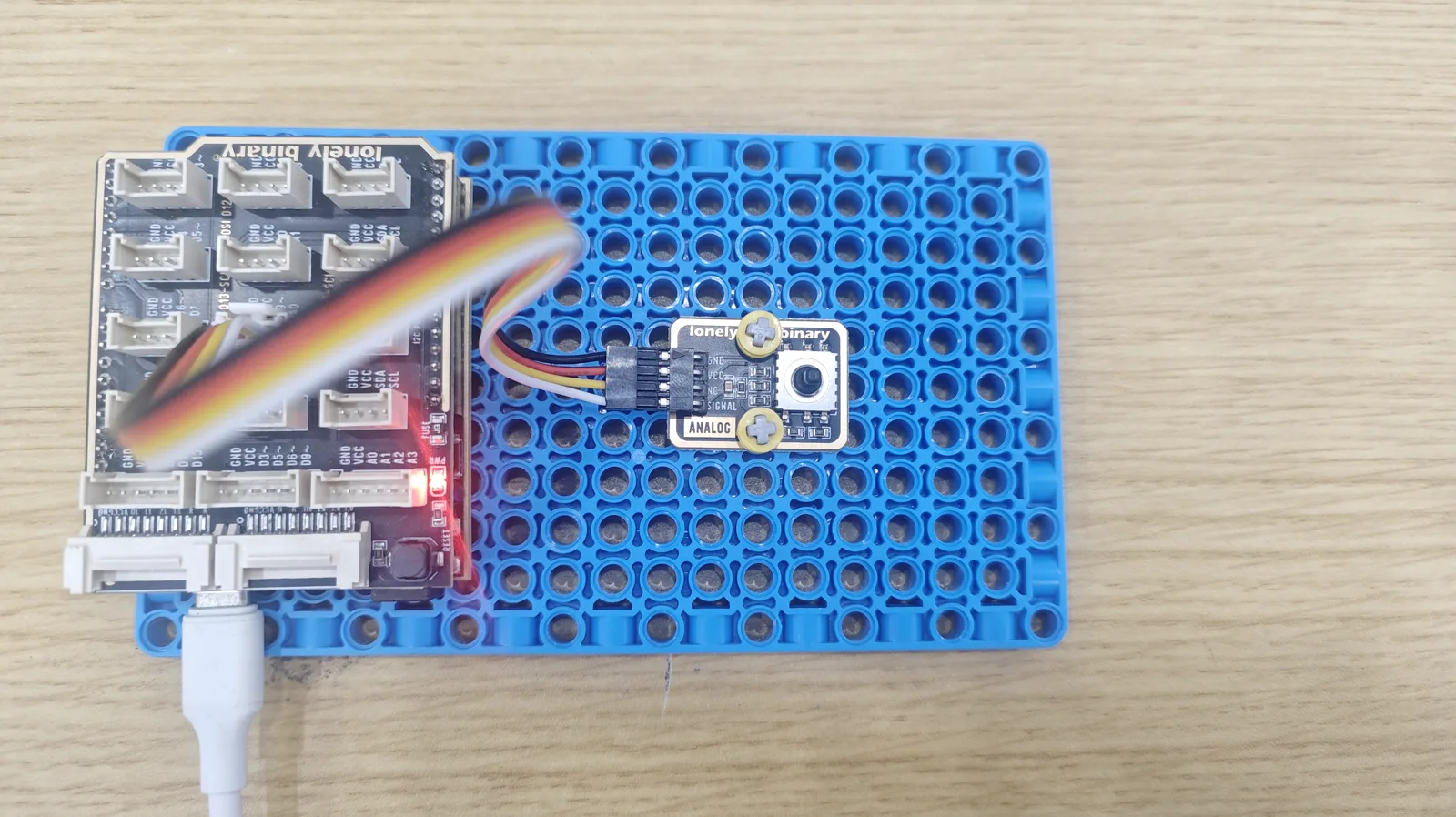
Serial monitor:
Five-direction joystick started
Up
Left
Down
Right
Press
Center
...
Moving the joystick prints the direction; LED turns on or off accordingly.
Note: TK61 IR Speed Sensor is different (count/speed); you can try it separately.
Proceed to Lesson 35.
Edit this page — content/guides/tinkerblock-workshop/34-joystick.mdx
Questions about this product
See what other owners have asked, and read their solutions.
This page covers several products. Choose yours to see the right discussions.
Discuss this article
Ask about this page. The answer stays here, on the page it belongs to, for whoever hits the same wall next.