The two boards
Eighteen boards fixed at 3.3 V and six you set yourself, the same size and the same three pins. Flip one over to tell them apart. The one with the LED gives 3.3 V; the one with the trimmer gives whatever you set.
One panel, two kinds
The twenty-four boards arrive joined in a single panel. One row of six is the adjustable board; the other eighteen are fixed at 3.3 V. Snap off what you need.
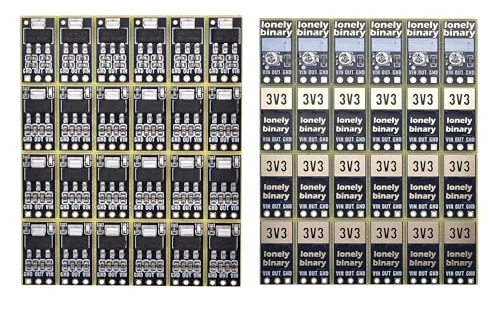
Both boards are 9.0 × 16.5 mm, with the same chip in the same place and the same three holes along one end. Pick a board and a part:
The 3V3 board
An AMS1117-3.3, two capacitors on each side of it, and a red LED with its 1 kΩ resistor. The LED is on the output, so it shows that the regulator is working, not just that power is arriving.
The ADJ board
An AMS1117-ADJ and the same four capacitors on the front. On the back, a 2 kΩ trimmer and a 220 Ω resistor set the voltage, and a white panel waits for you to write down what you set it to.
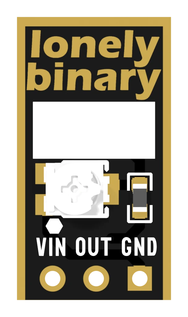
There is no LED. One would stay dark at the lowest settings, below the 1.8 V or so a red LED needs to light, so the only way to know what an ADJ board is putting out is to measure it.
When it does not work
Turn it over. The 3V3 board says 3V3 in a gold box on the back. The ADJ board has a small white trimmer and a blank white panel there instead. From the front, only the 3V3 board has an LED.
It is meant to be. A 1 kΩ resistor limits it to 1.5 mA at most, enough to see in a room and small enough not to matter to a battery. It is lit whenever there is voltage on OUT.
If the header pins are loose in your box, yes: cut a strip of three and solder it to each board you use. Three joints, and the board then sits in a breadboard like any other module.
Set to 3.3 V it works as one, but a trimmer can be knocked and the 3V3 board cannot, and the ADJ board has no LED to show it is on. Use the 3V3 boards for 3.3 V and keep the six ADJ boards for everything else.
Which is which from the front, why the back reads the other way, and what each mistake does.
Three pins: GND, OUT, VIN →Edit this page — content/books/ams1117/the-two-boards.mdx
Questions about this product
See what other owners have asked, and read their solutions.
AMS1117 LDO Regulator Kit, 24 Boards (18 × 3.3 V, 6 × Adjustable)
Loading discussions…
Discuss this article
Ask about this page. The answer stays here, on the page it belongs to, for whoever hits the same wall next.