A 3.3 V rail from an Arduino Uno
An Arduino Uno is a 5 V board, and a 3.3 V part on the same breadboard needs its own 3.3 V. A 3V3 board fed from the Uno's 5V pin makes a 3.3 V rail, and a short sketch lets the Uno measure it — as long as you know what the Uno is measuring against.
What goes where
| From | To |
|---|---|
| Uno 5V | 3V3 board VIN |
| Uno GND | 3V3 board GND, and the breadboard's GND rail |
| 3V3 board OUT | Uno A0, and the breadboard's 3.3 V rail |
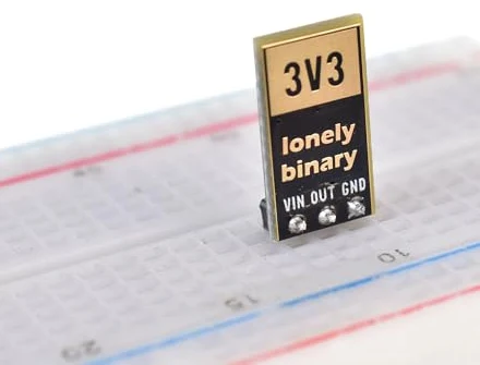
The board stands upright in the breadboard on its three pins, one row each. Push it in with the parts facing you, so the pins read GND, OUT, VIN left to right, and wire by the rows.
Upload, then load it
Upload the sketch and open the serial monitor at 9600 baud. With nothing on the rail, it should say about 3.30 V: the board's LED is the only load.
Then put a resistor across the two rails and watch the number:
220 Ω draws 15 mA and 100 Ω draws 33 mA — about a tenth of a watt in the resistor, which a common quarter-watt resistor takes in its stride. The output stays at 3.30 V throughout. That is the regulator doing its one job: the part draws more, the chip opens up to match, and the voltage does not move.
Why the number is not quite 3.30
The Uno's analog pin does not measure volts. It measures what fraction of its own 5 V supply the pin is at, from 0 to 1023, and the sketch multiplies back up by 5.0. USB is allowed to be anywhere from 4.75 V to 5.25 V at the port, so the Uno's idea of 5 V can be 5% out either way — and so can the reading.
Measure the Uno's 5V pin to GND with a meter, put that number in VREF, and
the reading will match the meter on OUT to within a few hundredths of a volt.
Now use the rail
Anything on the 3.3 V rail gets a steady 3.3 V. From 5 V the chip can supply about 480 mA before heat limits it, and the USB port and the Uno's own needs will usually limit you sooner. A 3.3 V sensor on I²C or SPI still needs its signals level-shifted to talk to a 5 V Uno: the logic level converter book is about exactly that.
The code
Reads the regulator's output on A0 twice a second and prints it. There is no library and nothing to configure; the only number to change is VREF.
// Wiring for this sketch (3V3 board, Arduino Uno).
//
//   Uno 5V   -> VIN
//   Uno GND  -> GND
//   OUT      -> Uno A0, and the breadboard's 3.3 V rail
//
// Arduino IDE: Tools > Board > Arduino Uno. No library, no other settings.

const float VREF = 5.0;  // the Uno's 5V pin, measured with a meter

void setup() {
  Serial.begin(9600);
}

void loop() {
  int raw = analogRead(A0);          // 0..1023 across 0..VREF
  float volts = raw * VREF / 1023.0;
  Serial.print("OUT = ");
  Serial.print(volts, 2);
  Serial.println(" V");
  delay(500);
}
analogRead gives a fraction of the Uno's own 5 V, not a voltage. If the reading is a little off, measure the Uno's 5V pin with a meter and put that number in VREF. 3.3 V on A0 is safe: the Uno's pins take up to 5 V.
When it does not work
A0 is not connected to OUT, or OUT has nothing on it. Check the LED on the board first: off means no input or a short, and the meter check page sorts out which. On means the A0 wire is in the wrong row.
Your USB port is giving the Uno a little under 5 V, and the sketch assumes exactly 5. Measure the Uno's 5V pin, put that in VREF and upload again. The regulator was right all along.
The serial monitor's speed does not match the sketch. Set the baud drop-down in the serial monitor to 9600.
From the Uno's USB, carefully. An ESP32 transmitting wants around 240 mA, the USB port is specified for 500 mA, and the Uno takes its own share first. Give the ESP32 a 100 µF capacitor across its 3V3 and GND, and if it resets on transmit, feed the 3V3 board from its own 5 V supply.
Two readings and an LED, and what each combination means.
Check it with a meter →Edit this page — content/books/ams1117/a-3v3-rail-from-an-uno.mdx
Questions about this product
See what other owners have asked, and read their solutions.
AMS1117 LDO Regulator Kit, 24 Boards (18 × 3.3 V, 6 × Adjustable)
Loading discussions…
Discuss this article
Ask about this page. The answer stays here, on the page it belongs to, for whoever hits the same wall next.