Three pins: GND, OUT, VIN
With the parts facing you the pins are GND, OUT, VIN, and the square pad is GND. Swap VIN and OUT and the LED still lights. Push the board in back to front and the supply is reversed. Both mistakes look the same until you measure.
GND, OUT, VIN
Hold the board with the chip facing you and the holes at the bottom. Left to right the pins are GND, OUT, VIN, and the square pad is GND. That is the same order as the chip's three legs above them. The wide metal tab at the top of the chip is OUT as well.
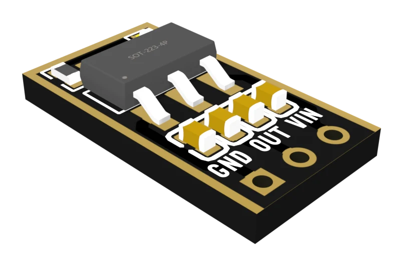
Three wires, one per pin:
- VIN to the supply's positive.
- GND to the supply's negative and to the ground of the part you are powering. One ground for everything.
- OUT to the part's supply pin.
Now try the two mistakes people actually make:
The LED does not check your wiring
It sits between OUT and GND. Put 5 V on OUT by mistake and the LED lights — brighter than usual — while the part on VIN is fed through a diode inside the chip that runs from OUT back to IN. The only check that means anything is a meter on OUT.
The back reads the other way

Both sides are labelled correctly for the side you are looking at. The trouble starts when the labels are read on one side and the board is pushed into the breadboard with the other side facing you. VIN and GND trade places, and the supply is reversed across the chip.
The chip limits its current and shuts down when it is too hot. Neither of those works backwards, and nothing else on the board protects against a reversed supply. The square pad is the quickest check: it is always GND, from either side.
When it does not work
Rewire it, connect only the supply, and measure OUT to GND. 3.3 V means the board came through. Check the 3.3 V part on its own too: it was fed over 4 V for as long as the mistake lasted.
The supply is reversed, usually because the board went in back to front. Unplug it, turn it round and measure OUT with nothing else connected. Anything but 3.3 V means the board is damaged — set it aside and use another.
Only an insulated one. The tab is OUT, not ground, so anything metal touching it is at 3.3 V and must not touch anything else. On a board this size the better fix is a lower input or a smaller current.
Why 5 V in is plenty for 3.3 V out, and a lithium cell is not.
The volt it needs to work →Edit this page — content/books/ams1117/three-pins-in-order.mdx
Questions about this product
See what other owners have asked, and read their solutions.
AMS1117 LDO Regulator Kit, 24 Boards (18 × 3.3 V, 6 × Adjustable)
Loading discussions…
Discuss this article
Ask about this page. The answer stays here, on the page it belongs to, for whoever hits the same wall next.