Specifications
| In the box | 24 boards: 18 × AMS1117-3.3 fixed at 3.3 V with a power LED, and 6 × AMS1117-ADJ adjustable. A mini screwdriver, male header pins and a storage case |
|---|---|
| Output | 3V3 board: 3.3 V (3.234–3.366 V). ADJ board: set with the trimmer, from about 1.25 V up to roughly 1 V below the input |
| Input | The output plus about 1.1 V, so 4.4–12 V for the 3V3 board. 12 V is the recommended maximum and 18 V the absolute maximum |
| Dropout | 1.0 V at 100 mA, 1.05 V at 500 mA, 1.2 V at 1 A, typical. 1.3 V worst case |
| Current | 1 A rated, but heat sets the real limit: about 480 mA from 5 V, 140 mA from 9 V and 90 mA from 12 V, in a 25 °C room |
| Heat | (VIN − VOUT) × current. At 120 °C/W, about 0.8 W takes the chip from room temperature to its 125 °C rating. Thermal shutdown near 150 °C |
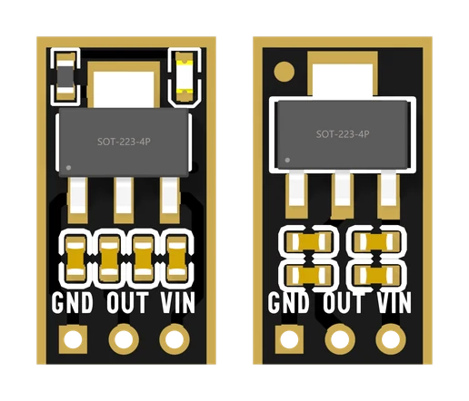
| Pins | GND, OUT, VIN, left to right with the parts facing you, on a 2.54 mm grid. The square pad is GND. From the back the order reads the other way |
| Standing current | About 5 mA for the chip whatever the load, plus up to 1.5 mA for the 3V3 board's LED or 5.7 mA through the ADJ board's resistors |
| Trimmer (ADJ) | 2 kΩ ±25%, single turn — about 270° from stop to stop. On the back, beside a 220 Ω resistor |
| Board | 9.0 × 16.5 mm. 10 µF and 100 nF on the input, the same on the output |
| Protection | Current limit and thermal shutdown. Nothing against a reversed supply |
What it does
A 3.3 V part — an ESP32 module, most sensors, most small screens — must not see more than about 3.6 V. The supply you have is usually 5 V from USB, or a 9 V battery, or a 12 V adapter. A regulator sits between them: it takes the higher voltage in and holds its output at a fixed lower one, however much current the part draws.
The AMS1117 does it by turning the difference into heat. That makes it simple, quiet and cheap, and it sets both of its limits: it needs about a volt more in than it puts out, and it can only shed so much heat.
The box
Twenty-four boards, joined in one panel. Snap off what you need.
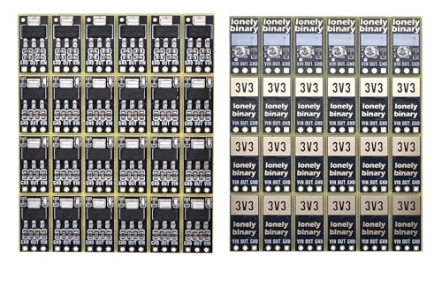
The 3V3 board (eighteen of them) gives 3.3 V and nothing else. A red LED on its output lights whenever there is voltage there.
The ADJ board (six) gives whatever you set with the trimmer on its back, from about 1.25 V up to a volt or so below the input. It has no LED, so a meter is the only way to know what it is putting out.
What it can run
| Supply | Most current at 3.3 V out | What that runs |
|---|---|---|
| USB, 5 V | about 480 mA | An ESP32 module, sensors, a small screen |
| 9 V battery | about 140 mA | Sensors; not Wi-Fi |
| 12 V adapter | about 90 mA | A sensor or two |
| One Li-ion cell | none — not enough headroom | Nothing at 3.3 V |
The limits in the middle column are heat, not the chip's 1 A rating: that is the current at which it reaches 125 °C in a 25 °C room. Where the extra volts go has the arithmetic, and when to use something else has the jobs it cannot do.
Wiring, in four lines
- VIN to the supply's positive, 4.4–12 V.
- GND to the supply's negative, and to the ground of the part you are powering.
- OUT to the part's supply pin.
- Then measure OUT to GND with a meter before you plug the part in.
With the components facing you the pins read GND, OUT, VIN, left to right, and the square pad is GND. From the back they read the other way, which is how a board ends up wired backwards. Three pins shows what each mistake does.
Setting the ADJ board
Supply on VIN, nothing on OUT but a meter. Turn the trimmer with the screwdriver from the box until the meter reads what you want, then connect the circuit. The trimmer turns about three quarters of a turn from stop to stop, not ten — set it with a meter explains why so much of that seems to do nothing.
Where to start
The handbook below is eleven short articles with a working figure in each. If you only read one, read the volt it needs: it is the answer to most "why is my output low" questions. If you are powering a 3.3 V part from an Arduino Uno, that build is written out start to finish.
When it doesn’t work
- The LED is on, but my 3.3 V part does not work.
- The LED sits on OUT, so it proves there is voltage there — not that the voltage is right. The commonest cause is VIN and OUT swapped: the supply goes into OUT, the LED lights brighter than usual, and the part on the VIN pin is fed about 4.3 V back through a diode inside the chip. Measure OUT to GND with a meter. If it is 3.3 V, check that the part's ground goes to the board's GND.
- Can I run an ESP32 from a 9 V battery with this?
- Not for long. An ESP32 transmitting draws around 240 mA, and 5.7 V of drop at that current is about 1.4 W of heat — nearly twice what the chip can shed, so it shuts itself down. From 9 V it can give about 140 mA and stay inside its rating. For a big drop, use a buck (step-down) converter.
- Can I power a 3.3 V project from one Li-ion or 18650 cell?
- No. The 3V3 board needs about 4.4 V in to make 3.3 V out. A cell is 4.2 V when full and spends most of its charge around 3.7 V, where the output sags to about 2.7 V — below the 3.0 V an ESP32 is rated for. Use a regulator with a few hundred millivolts of dropout, or a buck-boost.
- I turn the trimmer on the ADJ board and nothing changes.
- Three reasons, and they add up. It is a single-turn trimmer, about 270° from stop to stop, not a multi-turn one. The first and last tenth of its travel do nothing. And the output cannot rise within about a volt of the input, so with 5 V in, everything above roughly 4 V on the trimmer is dead travel. Watch a meter on OUT and turn slowly; do not force it past a stop.
- It is too hot to touch. Is it broken?
- Probably not. Half a watt makes this chip about 60 °C hotter than the room, which is too hot for a finger and well inside its 125 °C rating. It is only a problem if the output starts switching off and on — that is the thermal shutdown, and it means less current or a lower input.
- Do I need to add capacitors?
- No. Each board already has 10 µF and 100 nF on its input and the same on its output, which is what the chip needs to be stable. For a Wi-Fi board, a 100 µF capacitor across its own 3V3 and GND still helps: it covers the transmit bursts close to where they happen.