IN, OUT, and the pad that does nothing
Six pads at each end of the board, printed with the same six names in the same order. One of them is not connected, one changes name between the two headers, and that difference is the whole chaining story.
Both ends, printed
Every one of these boards has a header at each short edge. The back silkscreen marks them IN and OUT, in small white boxes at the corners, and prints the six pad names beside each:
| IN edge | OUT edge | What it is |
|---|---|---|
| GND | GND | Ground, shared with whatever drives it |
| VCC | VCC | 5 V in |
| CS | CS | Chip select — the MAX7219 datasheet calls this pin LOAD |
| DIN | DOUT | Data in on one edge, the same bits out the other |
| NC | NC | Not connected |
| CLK | CLK | Clock |
Five of the six names are identical on both edges. Only the fourth changes, and that is deliberate: because the rows are otherwise the same, a six-way jumper from one board's OUT to the next board's IN lands DOUT on DIN and joins everything else straight across. No crossover, no thinking.
The NC pad is the price of that symmetry. It goes nowhere on either edge. If you are counting holes against a tutorial that says "five-pin header" — most of them do, because the generic modules this board improves on have five — the sixth hole is the NC and you skip it.
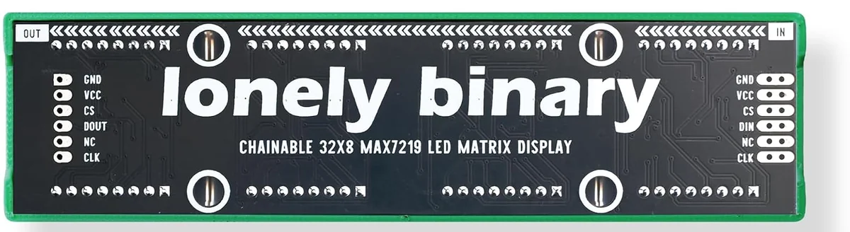
Wire to IN
Your microcontroller always goes to the IN edge. OUT is an output: it is this board repeating what it received, 16 and a half clock cycles later, for whatever is next in the chain. Wire a controller to OUT and nothing will ever reach the chips.
The headers arrive loose. The box has one long male strip to break up and three female sockets — enough to fit whichever end of whichever board you plan to use, rather than all six headers on all three boards. Solder them. Wires held in unsoldered holes make contact most of the time, and a display fed by data that is right most of the time shows nonsense rather than nothing, which is a much harder fault to recognise.
Three signal wires, however many boards
The point of the chain is that adding a board adds no wires to your controller. CS, CLK and DIN go to the first board and nowhere else; every board after it takes all six connections from its neighbour. Three boards chained is a 96×8 display on the same three pins.
The one thing that does not scale that way is current. Everything a chained board draws comes through its neighbour's VCC pad and the jumper between them, and four MAX7219s at full brightness is already a real load — how much current it wants has the arithmetic.
When it does not work
Check which header the wires are in. The two ends look identical from the front and are labelled OUT and IN in small white boxes on the back. Wired to OUT, the board's data pin is the chip talking rather than listening, and it will never receive anything.
The jumper has to run from the first board's OUT header to the second board's IN header. OUT to OUT does nothing. If the boards are side by side facing you, that means the jumper crosses from the left end of one to the right end of the next.
The pad marked NC connects to nothing. It exists so that the IN and OUT headers have the same six pads in the same order, which is what makes a chaining jumper a straight six-way ribbon instead of a crossover. Leave it empty.
It does — one long male strip and three female sockets in the box, none of them fitted. Push-fitting wires into unsoldered holes gives intermittent contact, which on a display looks like random flickering and garbage rather than an obvious open circuit. Solder them.
The wiring for an ESP32-S3 and for an Uno, the two libraries, and the shortest sketch that puts a word on the screen.
Five wires and a word →Edit this page — content/books/matrix-32x8/in-and-out.mdx
Questions about this product
See what other owners have asked, and read their solutions.
32x8 LED Matrix MAX7219, 3-Pack
Loading discussions…
Discuss this article
Ask about this page. The answer stays here, on the page it belongs to, for whoever hits the same wall next.