Specifications
| Display | 32 x 8 pixels per board — four 8x8 LED packages in a row, 256 LEDs |
|---|---|
| Driver | One MAX7219 per 8x8 square, four per board, cascaded DOUT to DIN on the PCB |
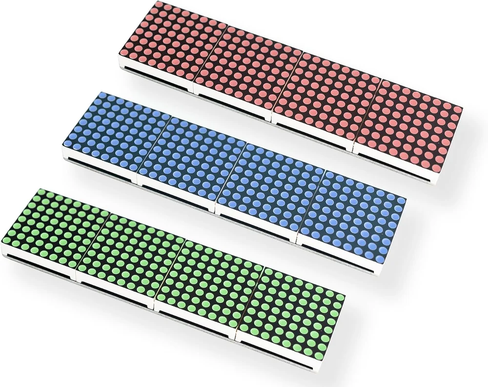
| In the box | 3 boards, one each in red, green and blue, with a 3D-printed case for each |
| Supply voltage | 5 V. The MAX7219's operating range is 4.0 to 5.5 V, so 3.3 V is outside it |
| Logic level | A HIGH must reach 3.5 V. A 5 V board clears it; a 3.3 V board is below the datasheet minimum and usually works anyway |
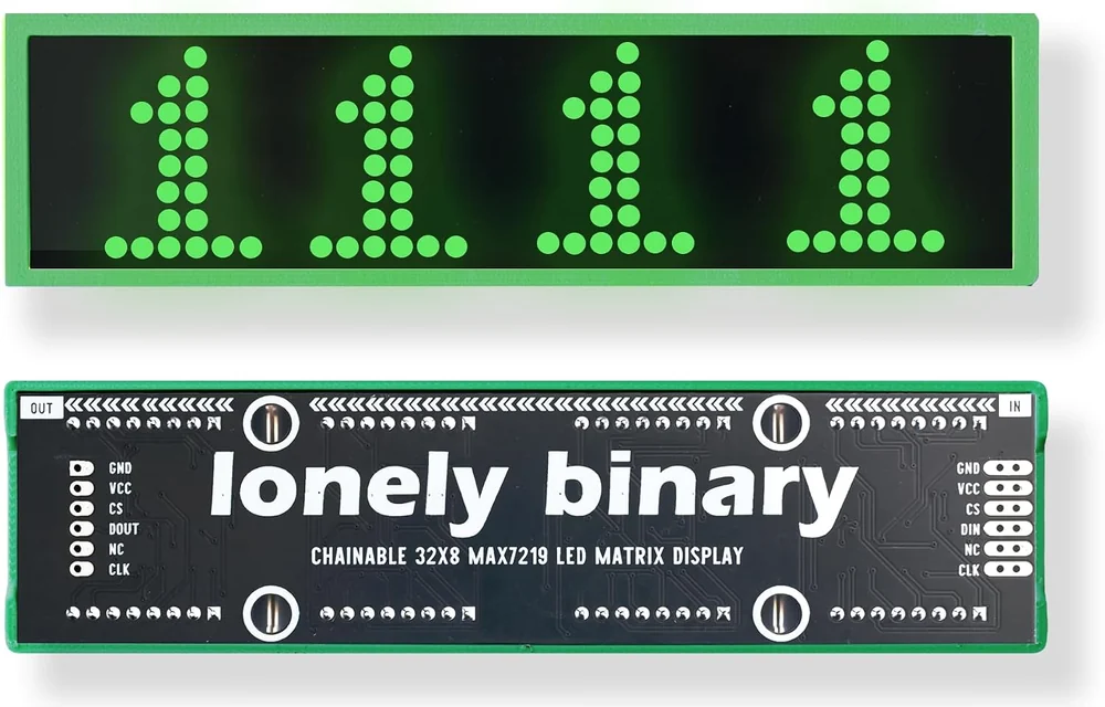
| Header | Six pads at each short edge, marked IN and OUT: GND, VCC, CS, DIN or DOUT, NC, CLK. Headers supplied loose |
| Signal wires | 3 — DIN, CLK and CS — however many boards are chained |
| Brightness | 16 levels, set in software. A duty cycle from 1/32 to 31/32, not a change in LED current |
| Scan rate | 800 Hz typical with all eight columns scanned, 500 to 1300 Hz specified |
| Clock | 10 MHz maximum, which is a 100 ns minimum clock period |
| Current | 330 mA typical per chip with every LED lit at full brightness; tens of milliamps for text at a normal setting |
| Board size | 12.8 x 2.5 x 1.0 cm |
What it is
A strip of four 8×8 LED matrices, 256 LEDs, with a MAX7219 driver chip behind each square. The four chips are cascaded on the board, so all four take their instructions from the same three wires — data, clock, and chip select — and so does every further board you chain onto the end.
The MAX7219 does the hard part. It holds the image in its own memory and scans it, one column at a time, about 800 times a second, so your board sends a frame and then has nothing more to do. Send a frame, unplug the data wire, and the picture stays.
What is in the box
Three boards — one red, one green, one blue — with a colour-matched 3D-printed case each, one long male pin header strip and three female sockets. The headers are not fitted; they are there to be soldered to whichever end of whichever board your project needs.
Each module is one fixed colour. Mixing colours means running more than one board, which is what the daisy chain is for.
The header
Six pads at each short edge, printed on the back, top to bottom:
| IN edge | OUT edge | What it is |
|---|---|---|
| GND | GND | Ground, shared with whatever drives it |
| VCC | VCC | 5 V in |
| CS | CS | Chip select. The MAX7219 datasheet calls this pin LOAD |
| DIN | DOUT | Data in on one edge, the same bits out the other |
| NC | NC | Not connected |
| CLK | CLK | Clock |
Only the fourth pad changes name, which is what makes a chaining jumper a straight six-way run from one board's OUT to the next board's IN.
Wiring, in five lines
- VCC to 5 V — not 3.3 V; the chip's supply range starts at 4.0 V.
- GND to your board's ground.
- DIN to a digital pin (GPIO 11 or D11 in the examples here).
- CLK to a digital pin (GPIO 12 or D12).
- CS to a digital pin (GPIO 10 or D10).
The NC pad gets nothing. Wire to the edge marked IN.
On an Arduino Uno that is the whole story. On an ESP32, a Pico or a Pi the three signal pins put out 3.3 V against a chip that specifies 3.5 V for a HIGH — three and a half volts is about what that means and what to do.
Where to start
The handbook below is ten short articles with a working figure in each. If you read one, read four squares in a row — most first failures on this board are one number in the sketch. If you want it lit in the next ten minutes, five wires and a word has the wiring and the sketch.
When it doesn’t work
- Only one quarter of the display lights up.
- The sketch declared fewer devices than the board has. A MAX7219 powers up in shutdown mode with its display blanked, so a chip nobody has addressed stays dark and looks broken. The count is 8x8 squares, not boards: 4 for one board, 8 for two chained.
- The text is rotated, mirrored or scrambled.
- That is the library's HARDWARE_TYPE, not the wiring. An 8x8 package can be mounted on its driver more than one way and the chip cannot tell, so MD_MAX72XX has to be told. This board is MD_MAX72XX::FC16_HW. If a display is lit and responsive but unreadable, everything electrical is already working.
- Can I run it from 3.3 V?
- Not the supply. The MAX7219's operating range starts at 4.0 V, so VCC goes to 5 V on every board. The signals are a separate question: a 3.3 V HIGH is below the chip's 3.5 V minimum, which is why an ESP32 driving this display is common, usually fine, and out of specification. If it flickers or shows garbage, shorten the wires or put a level shifter in DIN, CLK and CS.
- How many can I chain?
- As many as the power allows — the three signal wires do not change. What does not scale is current: a chained board draws everything it needs through its neighbour's VCC pad. Two on one jumper is fine at normal brightness; past that, run 5 V and ground to each board from the supply.
- Which end do I wire to?
- The one marked IN on the back. OUT carries DOUT, which is the chip talking rather than listening, so a controller wired there gets nothing through. The two edges are otherwise the same six pads in the same order, which is what makes a chaining jumper a straight six-way run.
- There are six holes and the tutorials say five wires.
- The fourth pad from the bottom on each edge is marked NC and connects to nothing. It is there so both headers have the same layout. Generic FC-16 modules have a five-pin header, which is why most write-ups say five.
- Do the three boards do different things?
- No. They differ only in LED colour — one red, one green, one blue. Each module is a single fixed colour, not an RGB display. The pinout, the code and every number on this page are the same for all three.