Four squares in a row
The board looks like one display. It is four, bolted edge to edge, each with a driver chip of its own — and almost every question this product raises is a question about that.
It is four displays
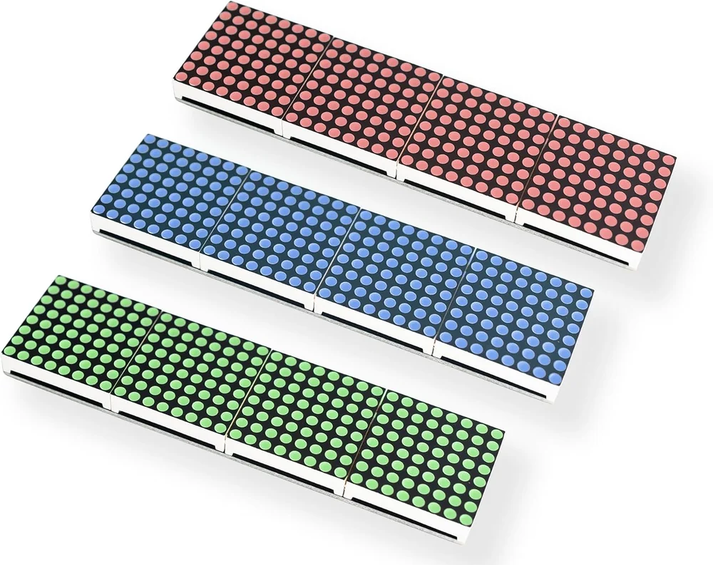
Turn the board over and the silkscreen says CHAINABLE 32X8 MAX7219 LED MATRIX DISPLAY. Turn it back and look along the light: there are three seams in it. Each of the four sections is a separate 8×8 LED package, 64 LEDs, with a MAX7219 driver chip of its own underneath. Four chips, 256 LEDs, one board.
They are joined the way any number of MAX7219s are joined — the data output of one goes to the data input of the next — so all four take their instructions from the same three wires. That is the good part. The part that catches people is that they are still four separate chips, and each one has to be woken up.
A MAX7219 powers up in shutdown mode with its display blanked and its scan limit set to one digit. The datasheet is blunt about it: program the driver before using the display, or it will sit there doing nothing. A chip the sketch never addressed never gets programmed, so it never lights.
What that number is counting
Every library for this chip wants to be told how many devices are on the wire. It is counting 8×8 squares, not boards:
| What you have | The number |
|---|---|
| One 8×8 module | 1 |
| One 32×8 board | 4 |
| Two 32×8 boards chained | 8 |
| All three in the box | 12 |
In the Arduino examples it is MAX_DEVICES; in MicroPython it is the third
argument to max7219.Matrix8x8(spi, cs, 4). Same count either way.
How big it is
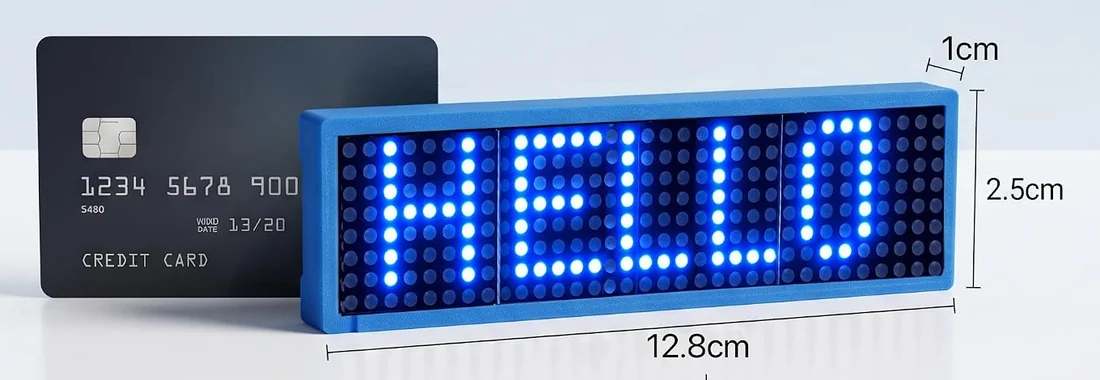
The listing puts it at 12.8 by 2.5 by 1.0 cm, which agrees with the dimensioned photograph below: half as long again as a credit card, and less than half as tall. The 3D-printed case in the box adds a few millimetres and a smoked front that raises the contrast a lot — unlit LEDs are a pale grey plastic, and the film hides them.
The three boards differ only in LED colour: red, green and blue, one each. The driver, the pinout, the code and every number in this book are the same for all three. Colour is not a setting — each module is one fixed colour, and mixing colours means running more than one board.
When it does not work
The sketch declared fewer devices than the board has. A MAX7219 powers up in shutdown mode with the display blanked, so a chip nobody has spoken to stays dark and looks broken. Set the device count to 4 for one board, 8 for two chained, and so on.
Same cause, one step further on. If the library thinks there are two squares and there are four, it writes into two of them and the other two keep whatever they had — usually nothing. Count the 8x8 squares on the front, not the boards in the chain.
That is the seam between two LED packages and it is physical, not a fault. Each 8x8 matrix is a moulded part with a rim, so four of them in a row have three joins in the light. The 3D-printed case and its smoked cover hide most of it.
Check the 5 V. Four chips at full brightness pull more than a board's 5 V pin comfortably gives, and the one furthest from the supply feels it first because the current for all four arrives through its neighbours' pads. How much current it wants has the numbers.
Six pads at each end, five of them useful, and one difference between the two headers that makes chaining a straight jumper.
IN, OUT, and the pad that does nothing →Edit this page — content/books/matrix-32x8/four-squares-in-a-row.mdx
Questions about this product
See what other owners have asked, and read their solutions.
32x8 LED Matrix MAX7219, 3-Pack
Loading discussions…
Discuss this article
Ask about this page. The answer stays here, on the page it belongs to, for whoever hits the same wall next.