Specifications
| Type | 4-digit 7-segment LED display with a TM1637 driver |
|---|---|
| Clock set | 6 panels with a colon between the middle digits and no decimal points, one each in yellow, green, blue, white, orange and red, with a film cover and a 3D-printed enclosure each |
| Digit set | 6 panels with a decimal point after each digit and no colon, in the same six colours, with a film cover and an enclosure each |
| TinkerBlock TK51 | The same board with mounting holes for the base plate, in the 46-piece kit |
| Driver chip | Titan Micro TM1637: 8 segments by 6 digits, of which this board uses 4 |
| Wires to your board | 4 — GND, VCC, and the 2 signal wires CLOCK and DATA |
| Protocol | Two-wire, TM1637's own. No addresses, so it is not I2C and cannot share an I2C bus |
| Supply voltage | 5 V for every colour. 3.3 V lights red, orange, yellow and green; blue and white need 5 V. The chip is specified at 4.5–5.5 V |
| Digit height | 0.56 inch, which is 14.2 mm |
| Brightness | 8 steps, set in software: pulse widths of 1, 2, 4, 10, 11, 12, 13 and 14 sixteenths |
| Board | 62.3 × 22.4 mm, four 4.6 mm mounting holes, 2.54 mm header at both ends |
What it does
Four digits, a driver chip and two wires. The chip holds the four bytes and does the refreshing itself, so your sketch sends a number once and the display keeps showing it through anything else the program goes on to do.
The protocol looks like I²C — a clock line, a data line, a start and a stop — and is not: there is no address anywhere in it. So an I²C scanner will not find this display, it cannot share a bus with I²C parts, and a second display needs a DATA pin of its own.
The boxes
Three products, one board. What differs is the display soldered to it.
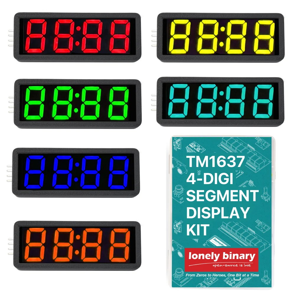
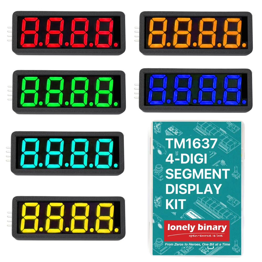
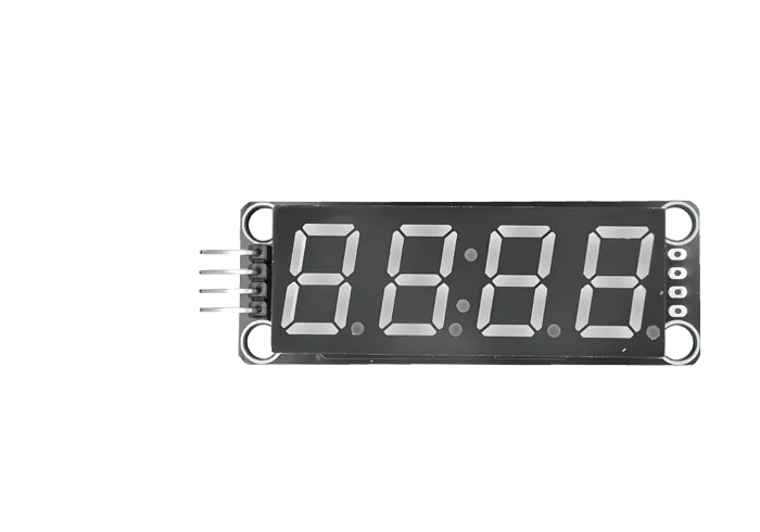
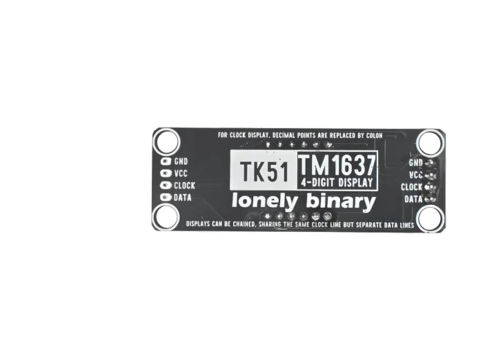
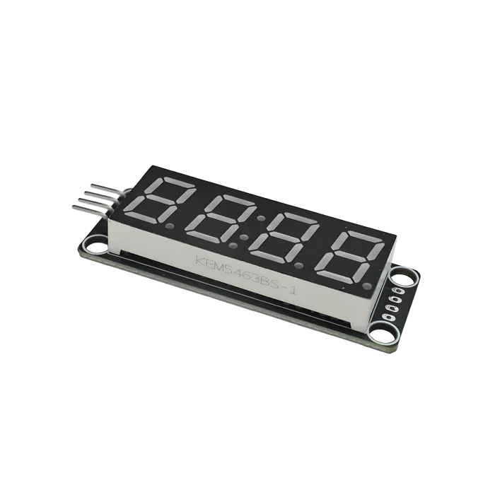
The TinkerBlock TK51, above, is the same board in the 46-piece kit. Its back carries the sentence that explains the whole range: for clock display, decimal points are replaced by colon. There are eight segment wires, and the eighth is either the points or the colon — never both.
Which panel
| You are showing | The set | Why |
|---|---|---|
| A time, a timer, minutes and seconds | Clock | The colon is the only separator that reads as a time |
| A temperature, a voltage, a weight | Digit | 23.5 needs a point, and a colon cannot be one |
| A count, a score, a raw number | Either | Neither separator gets used |
The same bit does both jobs: bit 7 of a digit is that digit's decimal point, and
on a clock panel the second digit's is wired to the colon. 0b01000000 — the
second digit — is what lights it. Not 0b10000000, which is the first digit and
does nothing at all on a clock panel.
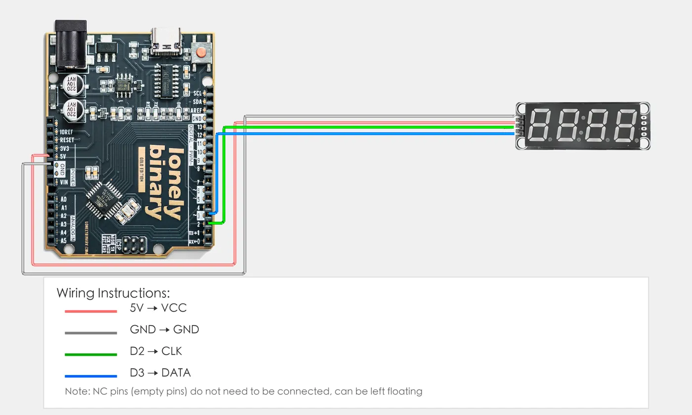
Wiring, in four lines
- GND to the board's GND.
- VCC to 5V on an Uno, 3V3 on an ESP32, ESP32-S3 or Pico.
- CLOCK to any digital pin — D2 on an Uno, GPIO 18 on an ESP32.
- DATA to any other digital pin — D3, or GPIO 19.
The pins are printed in that order, and the same order at both ends of the board. VCC is the one that is not free choice: the board's own 10 kΩ pull-ups tie CLOCK and DATA to it, so from 5 V beside an ESP32 both wires sit at 5 V against 3.3 V pins.
More than one
Displays share CLOCK and need a DATA pin each — six displays cost seven pins. A display only starts listening when its own DATA falls while CLOCK is high, so the clock toggling for its neighbour means nothing to it.
The four holes at the far end of each board are the same four nets as the header, not a pass-through. They are the right way to pass power and clock along a row, and the wrong way to feed the next display's DATA: wired that way, every panel shows the same number.
Example
Install TM1637 by Avishay Orpaz from the Arduino Library Manager — the
header is TM1637Display.h. The MicroPython version below drives the two wires
by hand and needs no library at all.
#include <TM1637Display.h>

#define CLOCK_PIN 2   // Uno D2.  ESP32: 18.  ESP32-S3: 4.
#define DATA_PIN  3   // Uno D3.  ESP32: 19.  ESP32-S3: 5.
#define COLON     0b01000000   // bit 7 of the second digit

// CLOCK first, then DATA.
TM1637Display display(CLOCK_PIN, DATA_PIN);

void setup() {
  display.setBrightness(4);          // 0 to 7, sent with the next lot of digits
  display.showNumberDec(1234);       // stays there with no further help
  delay(2000);
}

void loop() {
  // 12:34 on a clock panel, 12.34 on a digit panel — the same four bytes.
  // Leading zeros on, or a number below 1000 loses its leading digits.
  display.showNumberDecEx(1234, COLON, true);
  delay(1000);
  display.showNumberDecEx(1234, 0, true);
  delay(1000);
}from machine import Pin
import time
# Raspberry Pi Pico: CLOCK on GP0, DATA on GP1. Change for your board.
clk = Pin(0, Pin.IN) # released — the board's 10 kohm resistor holds it high
dio = Pin(1, Pin.IN)
DIGITS = (0x3F, 0x06, 0x5B, 0x4F, 0x66, 0x6D, 0x7D, 0x07, 0x7F, 0x6F)
def low(p):
p.init(Pin.OUT, value=0) # pull the wire down to 0 V
def high(p):
p.init(Pin.IN) # let go, and the resistor pulls it up
def pause():
time.sleep_us(100)
def write_byte(b):
for _ in range(8): # least significant bit first, unlike I2C
low(clk); pause()
if b & 1:
high(dio)
else:
low(dio)
pause()
high(clk); pause()
b >>= 1
low(clk); high(dio); pause() # ninth clock: the chip answers
high(clk); pause()
ack = dio.value() == 0
if ack:
low(dio)
pause()
low(clk); pause()
return ack
def start():
low(dio); pause()
def stop():
low(dio); pause()
high(clk); pause()
high(dio); pause()
def show(segments, brightness=4):
start(); write_byte(0x40); stop() # write, address steps itself
start(); write_byte(0xC0) # begin at the leftmost digit
for s in segments:
write_byte(s)
stop()
start(); write_byte(0x88 | brightness); stop() # display on, brightness 0-7
def number(n, colon=False):
segs = [DIGITS[int(c)] for c in "%04d" % (n % 10000)]
if colon:
segs[1] |= 0x80 # the colon is the second digit's point
show(segs)
while True:
number(1234, colon=True)
time.sleep(1)
number(1234)
time.sleep(1)Where to start
The handbook below is thirteen short articles with a working figure in each. If you only read one, read two sets, one board — it is the difference between the two six-packs and the reason most colons refuse to light. If you want a number on the display now, the first number is the whole build.
When it doesn’t work
- An I2C scan does not find it.
- It never will. The protocol has no addresses at all — the datasheet says as much — so there is nothing for a scan to answer. It uses two ordinary digital pins and the TM1637 library, and it cannot share SDA and SCL with real I2C parts.
- The colon will not light.
- Three causes, in order. The panel is a digit one and has decimal points instead of a colon. Or the mask is 0b10000000, which is the first digit — the colon is the second digit's point, 0b01000000. Or the number is 0 with leading zeros off, which makes the released library drop the dots entirely.
- Can I power it from 5 V next to an ESP32?
- No. The board's 10 kΩ pull-ups tie CLOCK and DATA to its VCC, so from 5 V both wires sit at 5 V against pins rated for 3.3 V. Feed it 3V3, or keep 5 V and put a bidirectional level converter in the two signal wires.
- The blue panel is much dimmer than the red one.
- Both are working. Blue and white LEDs need about 3.1 V before they conduct, and there are no series resistors on this board, so 3.3 V leaves almost nothing for the chip's own transistors. Titan Micro's datasheet asks for 5 V where blue is involved.
- setBrightness seems to do nothing.
- The brightness is only sent along with a lot of digits. Call setBrightness, then show something. On its own it changes a variable inside the library and nothing else.
- Two displays show the same number.
- They are sharing a DATA line. The four holes at the far end of the board are the same four nets as the header, so a second display wired from them hears every byte meant for the first. Displays share CLOCK and need a DATA pin each.