Specifications
| Chip | NXP PCA9685PW, TSSOP-28, with its internal oscillator: 25 MHz typical, no tolerance given |
|---|---|
| Channels | 16 PWM outputs, 12-bit: every period cut into 4096 counts. Each through 220 Ω to its pin; 25 mA sink and 10 mA source per pin at 5 V |
| PWM | One frequency shared by all 16 channels, 24 to 1526 Hz. 50 Hz for servos: prescale 121, about 4.88 µs a count. Powers up asleep, set to 200 Hz |
| Interface | I²C up to 1 MHz. SDA and SCL pulled up to VCC by 10 kΩ on every board. OE, active low, pulled to GND by 10 kΩ |
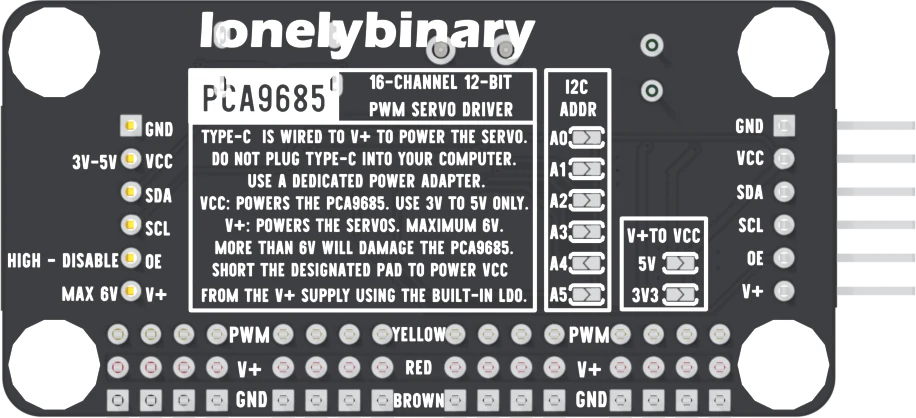
| Addresses | 0x40 out of the box. Six solder pads, A0 to A5, add to it; the datasheet counts 62 usable addresses. Never 0x70, the LED All Call address |
| Logic supply | VCC, 3 to 5 V, matched to the microcontroller, because VCC sets the voltage on SDA and SCL. Or bridge one V+TO VCC pad: 5V (ME6212C50) or 3V3 (ME6217C33), never both |
| Servo supply | V+, up to 6 V, on the red row and the header's V+ pin, with 1000 µF, 10 V across it. A 5 V, 3 A USB-C adapter for a few small servos; size for every servo stalled |
| Power inlets | A power-only USB-C socket with 5.1 kΩ on CC1 and CC2, so a USB-C charger gives 5 V, and a 5.0 mm two-way screw terminal. For an adapter, never a computer port |
| Protection | An AO3401A P-channel MOSFET blocks a reversed supply on both inlets. 220 Ω in series with every channel keeps a short to about 23 mA at 5 V |
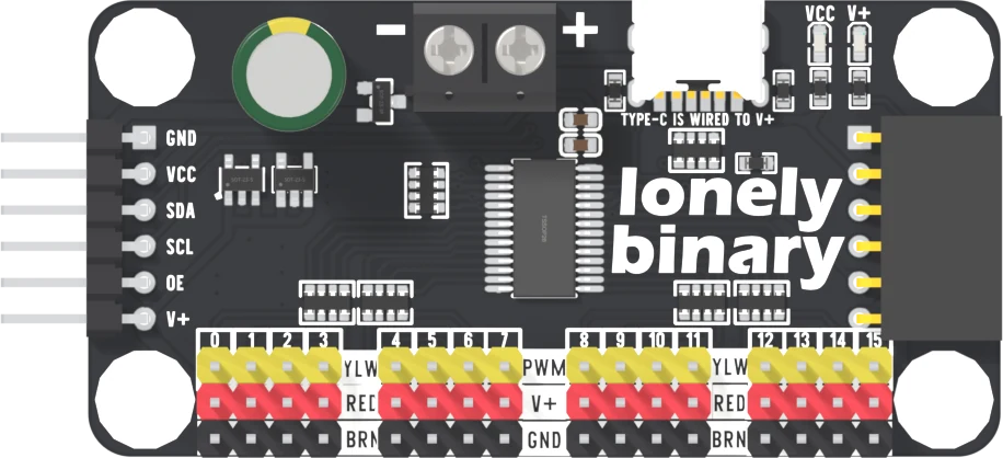
| Board | 64 × 32 mm, 1.6 mm thick; four 4.8 mm holes 56 × 24 mm apart; 13.61 mm tall at the capacitor. Six-pin male header on the left, the same six on a female socket on the right, 3 × 16 servo pins. Three boards a box, headers soldered |
| Revision | None printed; the model files are released as v1.0 |
What it does
A servo needs a pulse on its signal wire every 20 ms, for as long as it is meant to hold a position. This board makes sixteen of those pulse trains with a PCA9685 chip, on its own clock. The microcontroller writes a new pulse width over I²C only when a servo has to move, on two wires shared by every board on the bus.
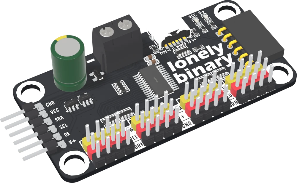
The box
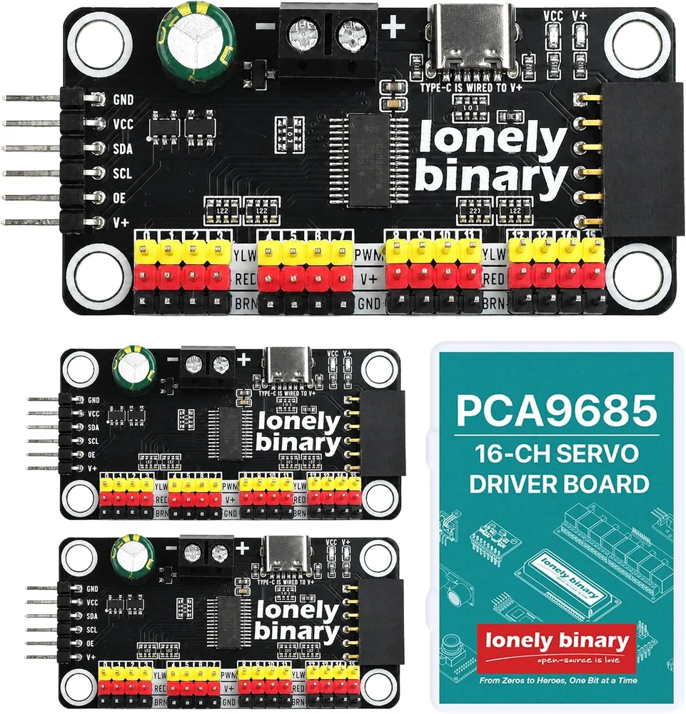
Three identical boards, 48 channels between them, every header already soldered. All three start at address 0x40.
Two faces
Wiring, in four lines
- GND to the microcontroller's GND.
- VCC to its 3V3 pin on a 3.3 V board, or its 5V pin on a 5 V board.
- SDA and SCL to its I²C pins: GPIO 8 and 9 on an ESP32-S3, A4 and A5 on an Uno.
- A 5 V adapter in the board's USB-C socket, and a servo on channel 0, brown or black wire on the bottom row.
The one rule
VCC sets the voltage on SDA and SCL. The board pulls both lines up to VCC, so VCC at 5 V puts 5 V on the microcontroller's I²C pins. Match VCC to the microcontroller. V+ is separate: it feeds only the servos, up to 6 V.
Where to start
The handbook below is thirteen short articles. V+ and VCC is the one to read before wiring anything. A pulse, not an angle explains why a first sketch makes servos buzz, and The first servo has one moving in a few minutes from an ESP32-S3 or an Uno.
When it doesn’t work
- What do I connect VCC to?
- To the microcontroller's own logic voltage: 3V3 on an ESP32 or a Raspberry Pi Pico, 5V on an Arduino Uno. VCC powers the chip, and SDA and SCL are pulled up to it, so VCC is the voltage your I²C pins see.
- Can I power the servos from my microcontroller or my computer?
- No. Servos can pull amps when they start or stall, which drags down whatever supplies them. Give V+ its own adapter in the USB-C socket or the screw terminal, and share only GND with the microcontroller.
- How big a power supply do I need?
- Add up the servos' stall currents. An SG90 stalls at about 0.65 A and an MG996R at about 2.5 A, so a 5 V, 3 A adapter suits a handful of SG90s, and sixteen SG90s need about 10 A. Keep V+ at 6 V or below.
- How do I use two or three boards on one bus?
- Give each its own address by bridging pads on the underside: none for 0x40, A0 for 0x41, A1 for 0x42. Plug them edge to edge, or join them with jumper wires, and create one driver object per address in the sketch.
- Why does my servo buzz at the ends?
- It has been sent a pulse wider than it can reach, usually the 150 and 600 counts from older tutorials, which are 732 and 2928 µs. Use writeMicroseconds() with 1000 and 2000 µs, and widen 50 µs at a time.
- Should I tell the library the oscillator is 25 MHz or 27 MHz?
- The datasheet gives 25 MHz typical and no tolerance, and Adafruit's example assumes 27 MHz. Neither is your chip. Start with 25 MHz, then measure one channel's period and set the oscillator from it: measured Hz × 4096 × (prescale + 1).
- Does it work with MicroPython?
- Yes. The chip is plain I²C registers; a MicroPython driver is in the examples of the Lonely-Binary/Servo-and-Motor repository on GitHub.