V+ and VCC
The board has two supplies. V+ carries the servos' current and never goes near the chip. VCC powers the PCA9685 and is also what SDA and SCL are pulled up to, so VCC decides the voltage on your microcontroller's I²C pins. Match it to the microcontroller: 3.3 V for an ESP32, 5 V for an Uno.
Two rails, two jobs
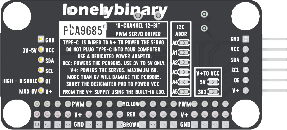
V+ is the servo supply. It comes in through the screw terminal or the USB-C socket, and it reaches the middle row of the servo field, the V+ pin on the control header, and the blue LED. The underside says MAXIMUM 6V, and MORE THAN 6V WILL DAMAGE THE PCA9685.
VCC is the chip's supply. It reaches the PCA9685, a 10 µF and a 100 nF capacitor beside it, and the red LED. The printed range is 3 V to 5 V.
They are kept apart because servo current is large and uneven. A servo starting to move pulls its supply down for a moment. On V+, that dip reaches only other servos. The chip and the microcontroller sit on VCC, out of the way.
The rule: VCC sets the bus voltage
The SDA and SCL lines each have a 10 kΩ pull-up resistor on the board, and both go to VCC. I²C devices only ever pull a line LOW; the resistor is what pulls it HIGH again. So HIGH on SDA and SCL is whatever VCC is.
That puts VCC straight onto your microcontroller's pins:
| Microcontroller | Its logic | VCC should be |
|---|---|---|
| ESP32, ESP32-S3, Raspberry Pi Pico | 3.3 V | 3.3 V |
| Arduino Uno, Nano, Mega | 5 V | 5 V |
An ESP32's pins are not built for 5 V. With VCC at 5 V, every idle moment of the bus holds 5 V on two of them. It may well appear to work, and the pins are overstressed the whole while.
The pulses on the servo field swing between 0 V and VCC too, so VCC is also the height of every servo signal.
Three ways to make VCC
From the microcontroller. Wire the header's VCC to the 3V3 or 5V pin. This is how every build in this book is wired, and it keeps VCC at exactly the microcontroller's logic level.
From V+, through the 3V3 pad. On the underside, a box printed V+TO VCC has two solder pads. Bridging the one printed 3V3 connects a 3.3 V regulator (ME6217C33, up to 800 mA) from V+ to VCC. The header's VCC pin then needs no wire, and it is the right choice for a 3.3 V microcontroller.
From V+, through the 5V pad. Bridging 5V connects a 5 V regulator (ME6212C50) instead. It needs about 100 mV above its output to regulate, so from a 5 V adapter VCC sits a little below 5 V. Only for a 5 V microcontroller.
Two things never to do
- Never bridge both pads. Both regulators run whenever V+ is present, so both bridged joins 5 V to 3.3 V through two regulators fighting.
- Never bridge a pad and also wire VCC. The regulator and the microcontroller then both drive VCC, and one of them pushes current into the other. Leave both pads open whenever VCC comes from a wire.
The 5 V regulator sits on V+ whether or not its pad is bridged, and its input is rated to 6.0 V. That is why V+ stops at 6 V even when you never touch the pads.
A bridged pad makes the chip depend on the servo adapter: unplug the adapter and the chip loses its settings. Both ways still need GND wired to the microcontroller.
When it does not work
V+ is up but VCC is not, so the chip is unpowered and will not answer on I²C. Wire the header's VCC to the microcontroller's 3V3 or 5V pin, or bridge one V+TO VCC pad on the underside.
That joins the output of the 5 V regulator to the output of the 3.3 V one, and they fight. Remove both bridges with solder wick, check the pads are apart with a meter, and bridge at most one.
Its SDA and SCL pins have been pulled up to 5 V, which they are not rated for. Move VCC to the 3V3 pin or the 3V3 pad, then check the ESP32 still finds the board on a scan. If it does not, test those two pins with another I²C device.
A bridged V+TO VCC pad makes VCC from V+, so no adapter means no chip. If the board must keep its settings without servo power, leave both pads open and take VCC from the microcontroller.
The screw terminal, the USB-C socket, and the transistor that protects both from a reversed supply.
The power inlets →Edit this page — content/books/pca9685/v-plus-and-vcc.mdx
Questions about this product
See what other owners have asked, and read their solutions.
PCA9685 16-Channel Servo Driver Board, USB-C Powered
Loading discussions…
Discuss this article
Ask about this page. The answer stays here, on the page it belongs to, for whoever hits the same wall next.