What is in the box
Three identical boards with their headers already soldered, and a printed QuickStart card. Each board has a six-pin control header on the left, the same six on a socket on the right, sixteen servo channels along the bottom, and two ways in for servo power along the top.
Three boards and a card
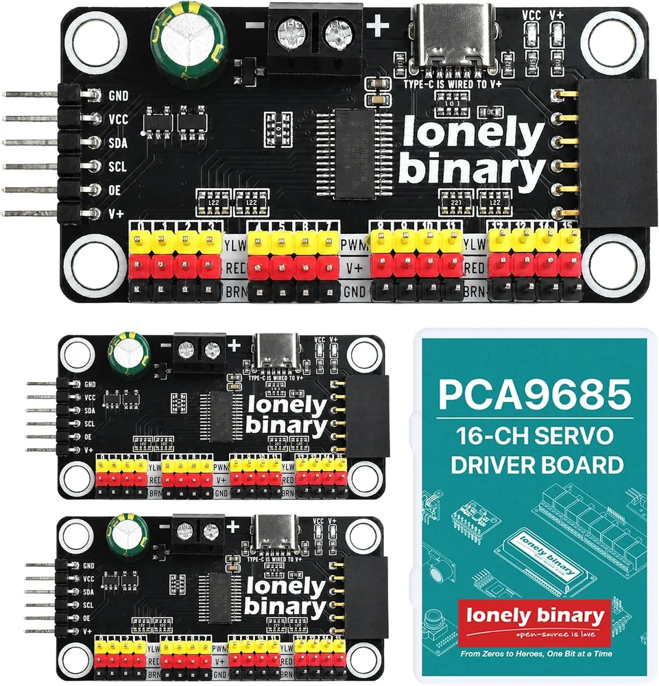
The three boards are the same board. Each drives sixteen servos, so the box is 48 channels. Out of the box every board answers at the same I²C address, 0x40: to use two on one bus, one of them needs a solder bridge first (Six pads, one address).
One board, face up
Read the board from the top, with the screw terminal at the top edge.
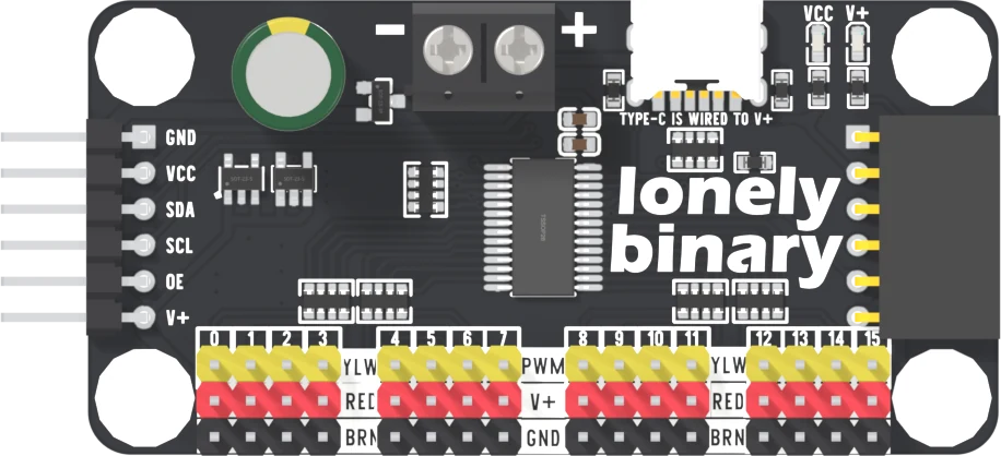
- Left edge: a six-pin right-angle male header, the control header. Top to bottom: GND, VCC, SDA, SCL, OE, V+.
- Right edge: a six-pin right-angle female socket with the same six signals in the same order. The male header of the next board plugs straight into it, so boards chain edge to edge (Chaining boards).
- Top edge: a 5.0 mm two-way screw terminal, printed − on the left and + on the right, and a USB-C socket. Both are inlets for servo power, and the print beside the socket says so: TYPE-C IS WIRED TO V+.
- Top-right corner: two LEDs, red for VCC and blue for V+.
- Bottom edge: the servo field, three rows of sixteen.
The servo field
Channel numbers 0 to 15 are printed above the pins, left to right. Each channel is a column of three:
| Row | Header colour | Printed | Carries |
|---|---|---|---|
| Top | yellow | YLW, PWM | the channel's pulse |
| Middle | red | RED, V+ | servo power |
| Bottom | black | BRN, GND | ground |
That is the order of a standard servo plug: signal, power, ground, with power in the middle. The labels between the blocks name the servo wire colour that goes on each row.
Every channel's pulse passes through a 220 Ω resistor between the chip and the pin. A channel shorted to ground by a stray wire is limited to about 23 mA at 5 V, inside the 25 mA the chip's output can sink. The same resistor lets an LED sit straight on a channel. Wire it from VCC to the PWM pin: the chip sinks 25 mA but sources only 10 mA. Wired that way the brightness runs backwards, since the LED lights while the pin is LOW.
The underside
The bottom face carries the warnings, the six address pads printed I2C ADDR, and two pads in a box printed V+TO VCC. The address pads are in Six pads, one address and the V+TO VCC pads in V+ and VCC. Neither needs touching for the first servo.
Size
64.00 × 32.00 mm and 1.60 mm thick, with four 4.80 mm mounting holes 4.00 mm in from each edge, which puts them 56 × 24 mm apart. The tallest part is the 1000 µF capacitor, 13.61 mm above the underside.
When it does not work
Brown or black wire on the bottom row, printed BRN and GND. Red in the middle, on V+. The orange, yellow or white signal wire goes on the top row, printed YLW and PWM. The red wire is always in the middle, so a servo plugged in backwards is not shorted, but it will not move.
Top to bottom, on both edges and on both faces: GND, VCC, SDA, SCL, OE, V+. The names are printed beside the pins on the top and again on the underside, where VCC, OE and V+ also carry a short warning.
Red, printed VCC, lights when the chip has its supply. Blue, printed V+, lights when the servo supply is present. They are the first thing to look at when nothing moves, because each one proves a different rail.
Yes. Every header is fitted: the male header takes female jumper wires, the servo rows take servo plugs, and the terminal takes bare wire. The only soldering you might ever do is on the address and VCC pads underneath.
What the width of a pulse means to a servo, and why the numbers in old tutorials make it buzz.
A pulse, not an angle →Edit this page — content/books/pca9685/whats-in-the-box.mdx
Questions about this product
See what other owners have asked, and read their solutions.
PCA9685 16-Channel Servo Driver Board, USB-C Powered
Loading discussions…
Discuss this article
Ask about this page. The answer stays here, on the page it belongs to, for whoever hits the same wall next.