Six pads, one address
Every board leaves the factory at 0x40. Six solder pads on the underside, A0 to A5, add 1, 2, 4, 8, 16 and 32 to that when bridged, so two boards on one bus need at least one bridge between them. One combination, 0x70, is also the chip's broadcast address and is never safe to use.
Where the pads are
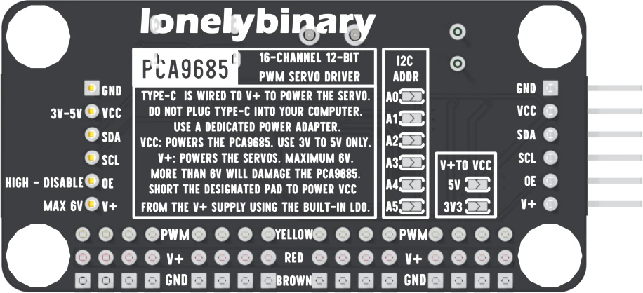
Turn the board over. The column printed I2C ADDR holds six pads, A0 at the top to A5 at the bottom. Each pad is two halves with a gap between them.
Open is 0, bridged is 1
Each of the chip's six address pins has a 10 kΩ resistor to GND, so an open pad reads 0. A blob of solder across the gap connects that pin to VCC, and it reads
- The address is 0x40 plus the bridged pads' values:
| Pad | Adds |
|---|---|
| A0 | 1 |
| A1 | 2 |
| A2 | 4 |
| A3 | 8 |
| A4 | 16 (0x10) |
| A5 | 32 (0x20) |
For the three boards in the box: leave one open (0x40), bridge A0 on the second (0x41), and bridge A1 on the third (0x42). Solder with the board unpowered and unplugged from everything.
The address to avoid: 0x70
Bridging A4 and A5 together gives 0x70. The PCA9685 has a second, shared address, LED All Call, that every chip answers at power-up so one write can reach all of them, and it is 0x70. A board jumpered there answers its own writes and everyone else's broadcasts. Never jumper a board to 0x70.
The datasheet counts 62 usable addresses. Other devices on the bus take some of the same range: check that no sensor already sits at the address you pick.
Talking to a second board
In the Adafruit library, each board is its own object with its own address:
Adafruit_PWMServoDriver left  = Adafruit_PWMServoDriver(0x40);
Adafruit_PWMServoDriver right = Adafruit_PWMServoDriver(0x41);
Call begin(), setOscillatorFrequency() and setPWMFreq() on each.
To see which pads a board really has, the
serial console example
in the Servo-and-Motor repository has a pca command that scans the bus and
prints the pad pattern for every board that answers.
When it does not work
Both are still at 0x40, so both answer every write and neither can be told apart. Bridge A0 on one of them to move it to 0x41, and create a second driver object at 0x41 in the sketch.
A blob that also touched a neighbouring pad sets two bits, or a joint that looks bridged is not. Run an I²C scan: the address it reports tells you which pads the chip actually sees. Look at the pads under a magnifier and reflow the one that disagrees.
It is probably at 0x70, which is also the All Call address every board answers at power-up. Unbridge A4 or A5 on it so it has an ordinary address.
Lay solder wick across the bridge, press it with the iron until the solder soaks in, and lift both together. Check with a meter that the two halves of the pad are apart before powering the board.
What changes on the bus and on V+ when boards plug into each other.
Chaining boards →Edit this page — content/books/pca9685/six-pads-one-address.mdx
Questions about this product
See what other owners have asked, and read their solutions.
PCA9685 16-Channel Servo Driver Board, USB-C Powered
Loading discussions…
Discuss this article
Ask about this page. The answer stays here, on the page it belongs to, for whoever hits the same wall next.