
IN, OUT, and the arrow between them
Both long edges of the board carry the same eight connections. One is marked IN, one OUT, and a row of chevrons between them says which way data travels. The ten bare pads are not yours.
Eight connections, printed twice
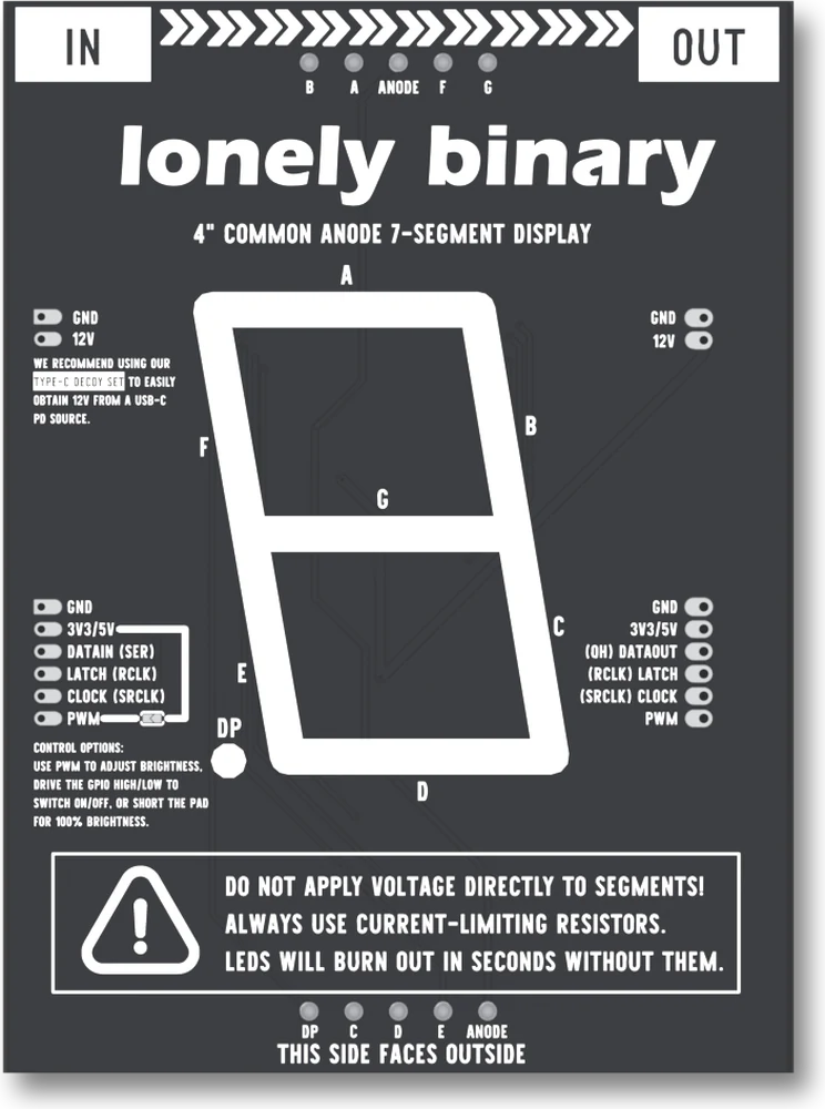
Turn the module over and every connection it has is on the left edge, and again on the right. The left is under a label reading IN, the right under OUT, and between them a row of chevrons points from one to the other.
Which board this is. This is the newer board, the one with the PWM pad. The earlier version of this display had no dimming: five signal pins, no PWM row, and no way to change its brightness. Everything about the digit, the shift register and the chain is the same on both; the brightness pages are about this board only.
The two-hole row is the segment supply: GND and 12V. The six-hole row is everything else, top to bottom as the back prints it: GND, 3V3/5V, DATAIN (SER), LATCH (RCLK), CLOCK (SRCLK) and PWM.
The names in brackets are the shift register chip's own, which helps the first time you read a 74HC595 datasheet and find nothing called DATAIN. PWM is the sixth wire, and the one this board adds: the digit is dark unless something says otherwise, and chapter 4 is about what.
Only one hole changes meaning
Compare the two edges and they are the same list in the same order, with one exception. Where the IN edge says DATAIN (SER), the OUT edge says (QH) DATAOUT. That is the shift register's serial output, the pin that hands bits on to whatever comes next. TI writes it QH′ in the datasheet; the board prints QH. The latch and clock are printed with the chip's names first on the OUT edge, because there they are being passed on.
Everything else, ground, the logic rail, the latch, the clock, PWM and the 12 V, is the same copper on both edges. It goes straight across the board. That is why a chain needs one power supply and one set of wires from your microcontroller no matter how long it gets, and also why one PWM wire dims every module in it.
Neither edge has a header fitted. The holes are bare, and solder the headers first is about what goes in them.
Common anode, and why you can ignore that
Under the brand name the board says 4" COMMON ANODE 7-SEGMENT DISPLAY. Common anode means the display's LEDs share their positive side, and a segment lights when something pulls its other end down to ground.
In a circuit you built yourself that would invert every byte in your table. Here it does not, because the driver, U2, is an inverting low-side driver: it sinks a segment's current to GND when its input is high. So a 1 in the byte lights a segment, the same as it would on a common-cathode display. The silkscreen is telling you what the part is, not what your code has to do about it.
The ten pads that are not for you
Along the top edge: B, A, ANODE, F, G. Along the bottom: DP, C, D, E, ANODE. Those are the display's own pins, with nothing in front of them. The warning printed beside them is not decoration: there is no resistor between these pads and the display, and an LED with no current limit lasts about as long as it takes to notice.
When it does not work
The one marked IN. Hold the board with the printing facing you and IN is on the left. Turn it over so the digit faces you and IN is on the right.
Then you have the earlier version, which has five signal pins and no dimming. This handbook is for the newer board: the brightness chapter does not apply to yours, and the rest of it does.
There are, and they are the same wire: one beside the 12V hole and one at the top of the signal row. Wire the 12 V supply's ground to one and your board's ground to the other and the board joins them for you, which is the shared ground the display needs.
The display's own ten pins: B, A, ANODE, F and G along the top, DP, C, D, E and ANODE along the bottom, as the back prints them. They have no resistor in front of them, which is what the boxed warning is about. Leave them alone.
The outline printed on the back puts DP on the left, where the lit digit has it at the bottom right. The letters are what count: A is the top bar, G the middle, DP the point. Light one segment at a time with a byte and compare.
The parts, in the order the signal meets them, and the ones that are not there.
What is on the board →Edit this page — content/books/seg4/in-and-out.mdx
Questions about this product
See what other owners have asked, and read their solutions.
4″ 7-Segment LED Display with 74HC595
Loading discussions…
Discuss this article
Ask about this page. The answer stays here, on the page it belongs to, for whoever hits the same wall next.