
Seven segments and a dot
A digit on this display is not a digit. It is eight separate lights with letters for names, and every byte in the rest of this handbook is those eight lights written down.
Eight lights, seven of them bars
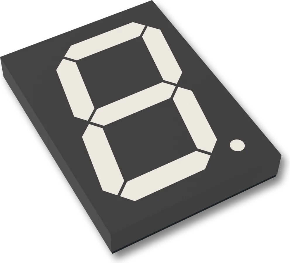
The display on this board has eight lights in it. Seven are bars arranged around the outline of an 8, and the eighth is the round dot at the bottom right. Nothing joins them. Each one can be on or off on its own, and the shapes we call digits are the ten combinations that happen to look like numbers.
They have names, the same on every seven-segment display: A across the top, B and C down the right, D across the bottom, E and F up the left, G through the middle, and DP for the point.
Press the letters and you will find what the ten digits cost. A 1 is two bars. An 8 is all seven. A 6 and a 5 differ by one bar, E, which is why a single dead segment can turn one into the other.
Why eight and not ten
Eight lights fit in one byte, one bit each, and a byte is the unit everything
behind the display moves in. The shift register under the display holds eight bits,
shiftOut() sends eight bits, and the table in the sketch is ten bytes long
because there are ten digits.
Bit 0 is segment A, bit 6 is G, and bit 7 is the point. The chain of ideas in this handbook is short: you write a number, your sketch turns it into a byte, the byte goes down one wire, and the lights it names come on.
What the board already knows
Nothing. It does not know what a 3 is. It switches eight lights on and off in whatever pattern arrives, and every pattern is equally valid to it, including the 246 that are not digits.
That is more often a feature than a nuisance. A minus sign is segment G on its
own. A degree symbol is A, B, F and G. Two modules showing E and 0 make a
perfectly good error message.
When it does not work
Send 0xFF, which is every segment plus the point. If exactly one stays dark, the fault is on the path of that one segment (its resistor, its channel of the driver, or the display) and not in your table. Try another module before you suspect the code.
On the front it is at the bottom right of the digit. The outline printed on the back puts DP on the left, so a reader comparing the two pictures thinks the point has moved. Go by the letters, not by where the drawing puts them.
Some of them. A, b, C, d, E and F all have shapes that seven bars can make, which is why hexadecimal on a 7-segment display is a solved problem. K, M, W and X do not, and no table will save you.
A segment this size will not light from a 5 V rail, and the board has a second supply for that.
Why it needs 12 volts →Edit this page — content/books/seg4/seven-segments-and-a-dot.mdx
Questions about this product
See what other owners have asked, and read their solutions.
4″ 7-Segment LED Display with 74HC595
Loading discussions…
Discuss this article
Ask about this page. The answer stays here, on the page it belongs to, for whoever hits the same wall next.