
The PWM pad
A new module with nothing wired to PWM is dark. The pad beside the PWM pin ships open, and the board gives you three ways to use it: bridge it, drive it high or low, or give it a PWM signal.
This is the newer board, the one with the PWM pad. The earlier version of this display had five signal pins and no PWM row, and no way to change its brightness. The digit, the shift register and the chain behave the same on both; this chapter is about the newer board only. If your back has no PWM pin and no boxed options, skip to the chain.
It ships open
On the back, beside the PWM pin of the IN edge, two small pads sit side by side. This is SB1, a solder jumper. One pad is on the logic rail, the 3V3/5V pin; the other is on the PWM pin. The silkscreen draws a line from the rail down to the pad and prints a box underneath.
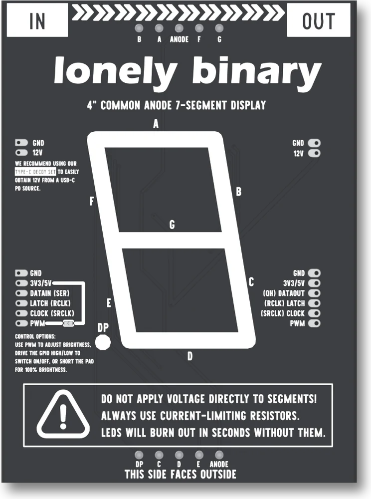
The pad ships open: nothing joins the two pads. That is read from the manufacturing files, not guessed from the part's name in the net list, which is "NC" and would suggest the opposite. The paste layer over the two pads is two separate polygons, no copper region spans them, and the board's own box says to short the pad for full brightness, which would be pointless if it were already shorted.
In the box, in the board's own order: use PWM to adjust brightness, drive the pin high or low to switch the digit on and off, or short the pad for full brightness.
Three ways, and the one nobody chose
Start with the first button, which is the board as it comes out of the bag. The pad is open and nothing is on PWM, so the pin floats, a 10 k resistor holds the dimmer switch off, and the digit is dark. A new module that lights nothing is usually this, not a fault.
The three ways are all ways of settling that pin:
- Short the pad. A blob of solder across the two pads ties the PWM pin to the logic rail, so the switch is always on. Nothing to wire. Do not also drive the pin from your board.
- Drive it high or low. Any output pin gives you on and off, and nothing between.
- Give it a PWM signal. The fraction of each period that the signal is high is the fraction of the time the digit is lit. The next two pages are about this.
A bridge is only solder, so it can be undone with braid or a pump.
In a chain
The PWM pin is one wire across the board, and so is the logic rail, and a chain's headers join both of them from module to module. That cuts two ways.
One PWM wire from your board dims every module in the chain together. You do not wire one per digit.
And a pad bridged on any module ties the whole chain's PWM wire to the rail. Every module is then at full brightness, and a PWM output wired to the chain is trying to drive a wire that is held high. Choose one: leave every pad open and drive PWM from your board, or bridge one pad and wire nothing to PWM.
When it does not work
Check the PWM pad first. It ships open, so with nothing wired to the PWM pin the dimmer switch is held off and the segments have no supply, whatever the shift register holds. Bridge the pad with solder, or drive the PWM pin high from your board.
A bridged pad ties the PWM pin to the logic rail, so the digit is always at full brightness and a PWM signal has nothing to change. Desolder the bridge with braid or a pump to get dimming back.
The pin must be an output that is driven high at least some of the time: an input, a pin that never leaves 0, or analogWrite on a pin that cannot do PWM all leave the switch off. Make the pin high with a plain digitalWrite first to separate the wiring from the signal.
A pad is bridged on one of the modules. The headers join the PWM nets, so one bridged pad holds the whole chain's PWM wire at the logic rail and every module is on full. Find the bridged pad and desolder it, or keep it and leave PWM unwired.
You have the earlier version of this module, with five signal pins and no dimming. It is always at full brightness once it has its 12 V, and everything in this chapter is about the newer board.
The two transistors and two resistors behind the pad, and why the digit comes back as it was.
How the dimmer works →Edit this page — content/books/seg4/the-pwm-pad.mdx
Questions about this product
See what other owners have asked, and read their solutions.
4″ 7-Segment LED Display with 74HC595
Loading discussions…
Discuss this article
Ask about this page. The answer stays here, on the page it belongs to, for whoever hits the same wall next.