
Specifications
| Digit height | 4 inch (about 100 mm), one digit per module. The board is about 90 x 122 mm |
|---|---|
| Display type | Common anode, as printed on the back. A 1 in the byte lights a segment: the ULN2803A driver inverts, so the board deals with the polarity |
| Segment supply | 12 V from its own supply, on the pins printed 12V. It passes straight across the board to the next module |
| Logic supply | 3.3 V or 5 V on the pin printed 3V3/5V, which feeds only the shift register (rated 2 V to 6 V), so the same wiring works from an ESP32 or an Uno |
| Wires to your board | 6 signal wires: GND, 3V3/5V, DATAIN (SER), LATCH (RCLK), CLOCK (SRCLK), PWM. 5 if you short the PWM pad, because PWM then needs no wire. The 12 V supply is two more |
| Dimming | A PWM pin, and a solder pad beside it. The pad ships open, so wire PWM or short the pad: with the pad open and nothing on PWM the whole digit is dark. High is on, low is off, a duty cycle is brightness. All segments dim together |
| Shift register | One 74HC595 8-bit shift register per module. QA to QG drive segments A to G and QH the decimal point |
| Driver | One ULN2803A per module: eight sinking drivers, 500 mA per channel absolute maximum. Each output goes through a 75 ohm resistor (510 ohm for the decimal point) to its segment |
| Segment current | Set by the 12 V less about 1 V across the driver and the segment's own forward voltage, over 75 ohm. It was not measured, so no milliamp figure is quoted here |
| Segment map | Bit 0 is segment A through to bit 6 segment G, and bit 7 is the decimal point. Sent MSBFIRST |
| Chaining | DATAOUT (QH) of one module to DATAIN (SER) of the next. Clock, latch, PWM, the logic rail, the 12 V and ground all carry on across the join, so one PWM wire dims every module |
| Headers | Loose in the bag: male strips to cut and female sockets. Both edges are bare through-holes and have to be soldered before anything is plugged into them |
What it is
A single 4-inch digit with its driver board behind it. The driver is a 74HC595 shift register and a ULN2803A: three ordinary output pins on your board become eight outputs on the module, one per segment, and the same three pins drive as many modules as you plug together. A fourth pin, PWM, sets how bright the whole digit is.
The digit needs 12 V. The shift register needs 3.3 V or 5 V. Those are two different supplies and the board takes them on two different headers, which is the single most important thing about wiring it. The third thing is the PWM pad, which ships open: the display stays dark until you short it or drive PWM.
The two edges
Both long edges carry the same eight connections. One is printed IN and one OUT, with a row of chevrons between them showing which way data travels.
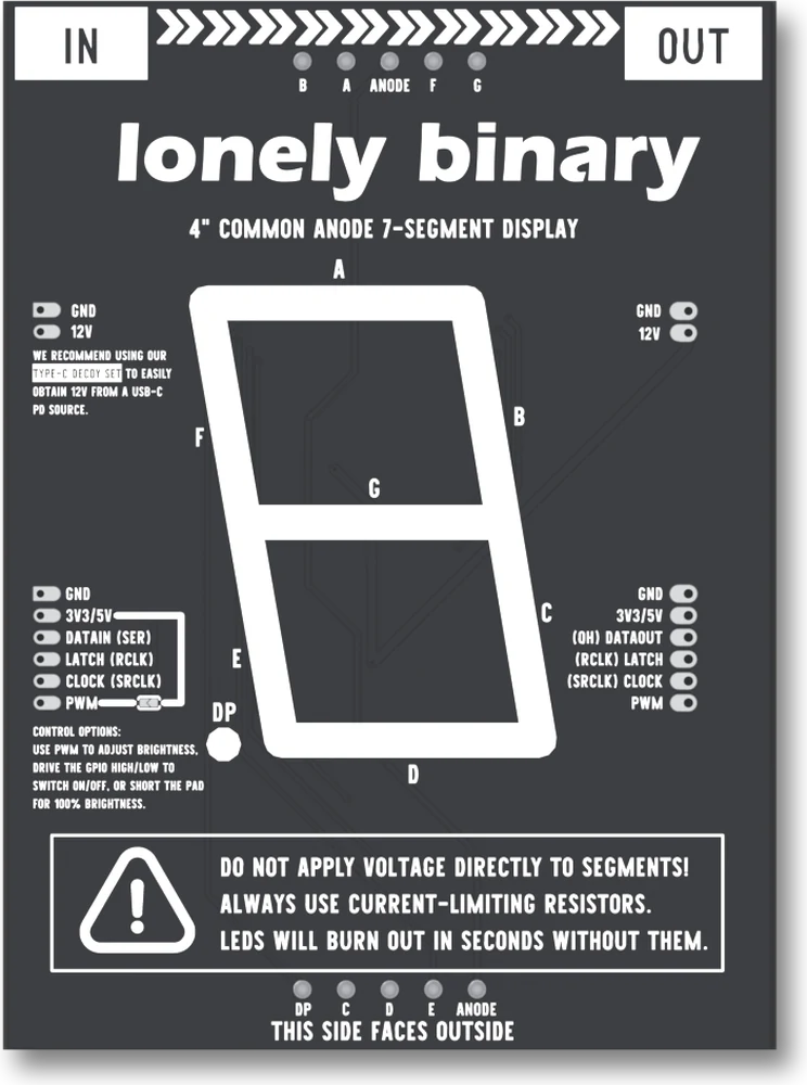
| Header | Pins, top to bottom as the back prints them |
|---|---|
| Power, two pins | GND, 12V |
| Signals, six pins | GND, 3V3/5V, DATAIN (SER), LATCH (RCLK), CLOCK (SRCLK), PWM |
The OUT edge prints the same list with three labels turned round: (QH) DATAOUT, (RCLK) LATCH and (SRCLK) CLOCK.
The ten bare pads along the top and bottom edges are not yours to wire. They are the display's own pins, and the box printed on the back says what happens if you feed one directly.
Wiring
- 12V and the GND beside it to a 12 V supply.
- 3V3/5V to your board's 3.3 V or 5 V pin, and the GND beside it to your board's ground.
- DATAIN (SER), LATCH (RCLK) and CLOCK (SRCLK) to any three digital outputs.
- PWM, one of two ways: solder the pad between 3V3/5V and PWM shut and wire nothing, for full brightness; or wire PWM to an output. High is on, low is off, and a PWM output gives any brightness in between. Do not do both.
That is six signal wires, or five with the pad shorted, and the 12 V pair.
The 12 V supply's ground and your board's ground have to be the same wire. Two separate grounds is the fault that half works. And a module with the pad open and nothing on PWM stays dark, which looks exactly like a fault in everything else.
Chaining
Put the OUT edge of one module against the IN edge of the next. The modules butt up against each other, so the digits sit at their natural spacing with no gap.
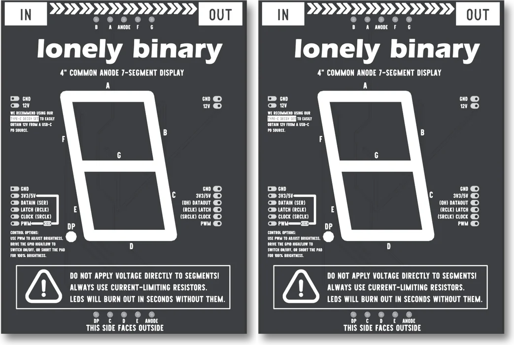
Everything except the data line is shared, so one latch pulse updates the whole chain at once, one 12 V supply feeds all of it, and one PWM wire dims every digit. Data is the exception: it goes out of a module on DATAOUT and into the next on DATAIN, and never back. The same sharing means a PWM pad shorted on any module holds the whole chain full on.
The headers in the bag
The headers come loose in the bag: male strips to cut to length and female sockets. Both edges are bare through-holes and have to be soldered. A jumper pressed into an unsoldered hole is a contact whose resistance changes every time the wire moves, which shows up as wrong segments, a module that works sometimes, or a chain where only the first one lights.
Where to start
The handbook below goes in order: what a digit is made of, why it needs a second supply, what is printed on the board and what is on it, how the shift register works, how the PWM pad and the dimmer work, how a chain works, and two builds. If you have the box open now, solder the headers first, then wire the two supplies. If the digit stays dark, the PWM pad is the first chapter of the brightness section, and when nothing lights puts it first on the list.
When it doesn’t work
- The board is dark and I have wired everything.
- Look at the PWM pad first. The board ships with it open, and with nothing on PWM the 12 V never reaches the display, whatever the shift register holds. Touch a wire from PWM to 3V3/5V with the 12 V on: if the digit lights, solder the pad shut for always on, or drive PWM from a pin. If it stays dark, check the 12 V at the 12V pin with the black probe on your board's GND. The earlier board has no pad, so start at the 12 V.
- Can I run it from the Arduino's 5 V pin?
- No. The segments run from the 12 V input through the driver and a 75 ohm resistor each. The 3V3/5V pin feeds the shift register only, and the segments' current never touches it. How a segment behaves on 5 V was not measured for this book, and the board is not built for it.
- Can I dim one segment?
- No. The dimmer is a switch between the 12 V and the display's common anode, so it switches every segment together. A duty cycle of 50 percent makes the whole digit lit half of every moment. What the shift register holds does not change, so the same digit comes back the instant PWM goes high.
- What if I have the earlier board?
- The earlier version of this display had no dimming: five signal pins, no PWM row, no pad. Everything about the digit, the shift register and the chain on this page and in the first chapters of the handbook is the same. The pages about the PWM pad and the dimmer are about this board only, and you do not have a pad to short or a pin to drive.
- Only the first module works.
- The chain is broken at the join. Data leaves a module on DATAOUT and enters the next one on DATAIN; it never goes back to your board. With everything off, check continuity from the first module's DATAOUT to the second module's DATAIN, and that the joint is soldered rather than pressed together.
- The two digits are the wrong way round.
- The byte you send first travels furthest. Each byte after it pushes the earlier ones one module further down the chain, so the last byte sent stays in the module your wires go to, which is the right-hand one when the digits are facing you. Fill the array so buf[0] is the leftmost digit.
- The segments light, but the shapes are wrong.
- Two candidates. If the pattern is steady and wrong, try the other bit order: LSBFIRST instead of MSBFIRST turns every byte into a different valid-looking one. If it changes when you nudge the bench, it is a connection: a jumper held in an unsoldered hole is a contact whose resistance moves, and the bits it drops read as zeros.
- Do I need a resistor?
- Not for anything you wire. Each segment has its own resistor on the module: the ULN2803A's outputs go through 75 ohm resistors (510 ohm for the point) to the display. The warning printed on the back is about the ten bare pads along the long edges, which are the display's own pins: put a voltage on one of those directly and that segment can burn out.
- What happens if I short the PWM pad and also drive PWM?
- Shorting the pad ties PWM to the logic rail, so a pin you drive into it is fighting a wire that is held high. Pick one. A pad can be undone by desoldering the bridge. In a chain the same applies across every module, because PWM is one wire through all of them.
- How many can I chain?
- There is no limit in the protocol: every module you add is one more shiftOut call before the same single latch pulse. The practical limits are the 12 V supply's current, which all of them share through the join, and the length of the wires between your board and the first module.