Specifications
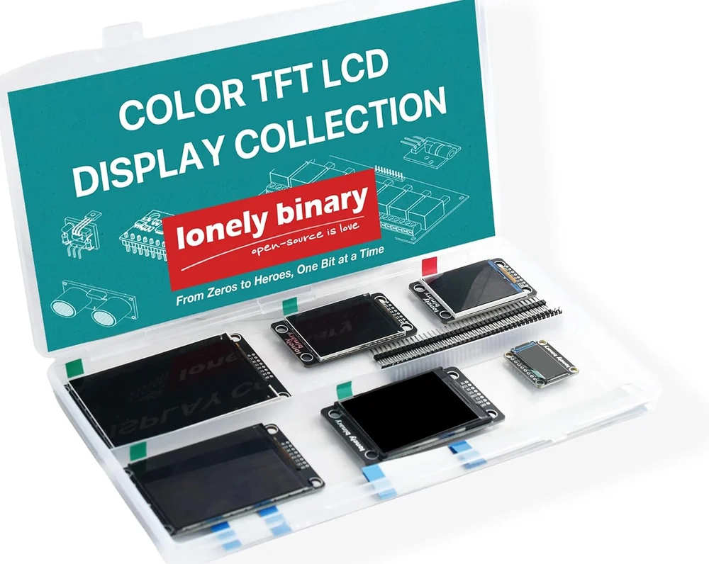
| In the box | 6 displays — 0.96″, 1.8″, 2.0″, 2.4″, 2.8″ and 3.5″ — with 9 FPC ribbon cables in three lengths, 2 straight and 2 right-angle breakaway header strips, and a hinged case |
|---|---|
| Sizes | Six diagonals from 0.96″ to 3.5″. The 2.0″, 2.4″ and 2.8″ are the same 240 × 320 on three sizes of glass; only the 3.5″ adds pixels, at 320 × 480 |
| Controllers | ST7735 on the 0.96″ and 1.8″, ST7789 on the 2.0″, 2.4″ and 2.8″, ST7796 on the 3.5″. No touch controller and no microSD socket on any board |
| Connector | Every panel ends in the same 15-pin FPC, pre-soldered, and breaks out to the same eight pads on 2.54 mm. Swapping panels moves no wires |
| Pads | BL, RST, DC, SCL, MOSI, CS, 3V3, GND, in that order. The clock pad is labelled SCL; there is no MISO, because nothing is read back |
| Logic level | 3.3 V only, printed on the back of every board. A 5 V board such as an Uno needs a logic level converter on all five signal lines or it will damage the panel |
| Colour | RGB565 — two bytes a pixel on the wire. A full redraw is about 10 ms on the 0.96″ and about 61 ms on the 3.5″ at the library's default clock, before anything else in the sketch |
| Backlight | PWM dimmable on every panel. The 0.96″ is wired active low and the other five active high, which the driver library resolves from the panel constant |
What it is
Six colour TFT displays, from a 0.96 inch strip to a 3.5 inch panel, that talk SPI and are interchangeable. Every one of them ends in the same 15-pin flat ribbon and breaks out to the same eight pads, so a circuit built around the smallest takes the largest without a wire moving.
What differs between them is a row in a table: which controller is behind the glass, how many pixels there are, how fast the bus may run, which way round the backlight is wired, and how far into the controller's memory the visible pixels start. The driver library resolves all five from one constant.
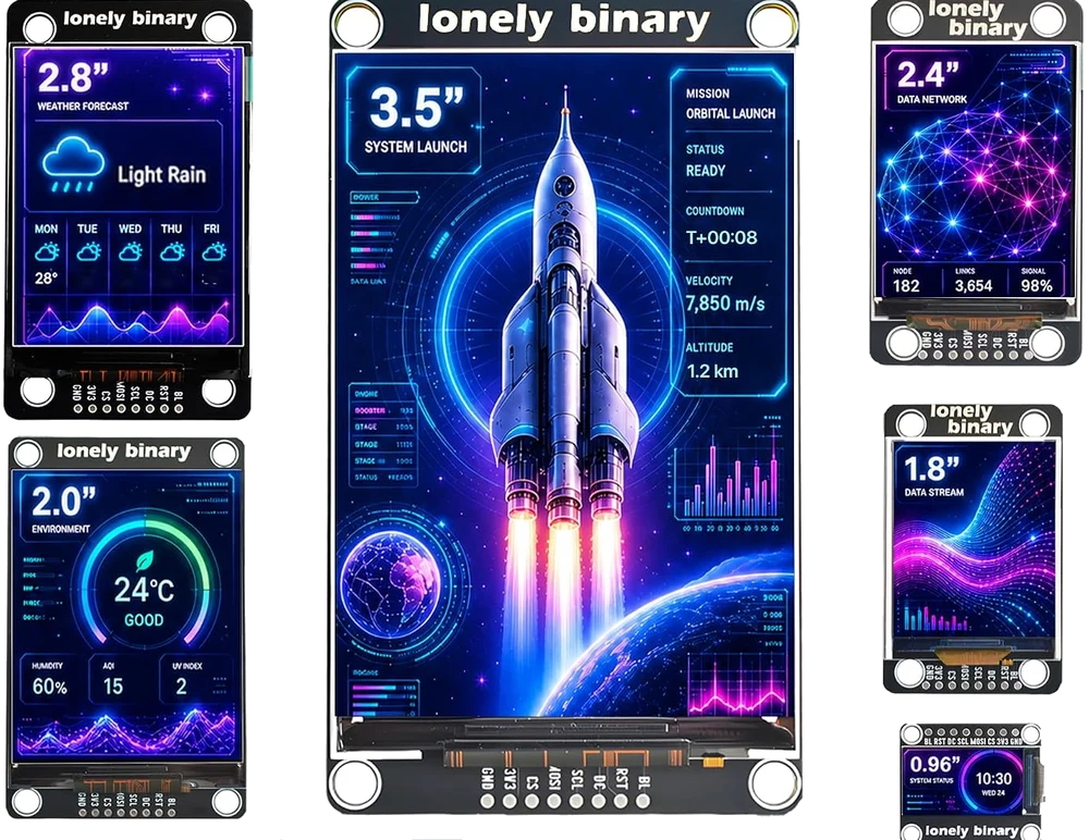
Which panel for which job
| Size | Resolution | Controller | Good for |
|---|---|---|---|
| 0.96″ | 80 × 160 | ST7735 | One reading — a temperature, a state word, a battery bar |
| 1.8″ | 128 × 160 | ST7735 | Four or five lines of text in something handheld |
| 2.0″ | 240 × 320 | ST7789 | The sharpest in the kit. A small dashboard that looks printed |
| 2.4″ | 240 × 320 | ST7789 | The default. Readable at a desk, quick to redraw |
| 2.8″ | 240 × 320 | ST7789 | The same picture spread wider, for reading across a room |
| 3.5″ | 320 × 480 | ST7796 | The main screen, at twice the pixels and twice the redraw |
The three middle panels are one picture at three physical sizes. Choosing between them is choosing how big a pixel is.
Wiring, in four lines
- 3V3 and GND to a 3.3 volt supply and ground. Never 5 V.
- SCL and MOSI to your board's SPI clock and data-out. There is no MISO.
- DC, RST and CS to any three spare GPIOs.
- BL to a spare GPIO to dim it, or to 3V3 to leave it lit.
Or one ribbon cable into an expansion board with a 15-way socket, and none of the above.
On an ESP32-S3 the library's defaults are GPIO 12, 11, 2, 42, 10 and 41 for those six signals; on a classic ESP32, GPIO 18, 23, 2, 4, 15 and 32. It picks between the two from the board you select in Tools, and there is no third set — on an ESP32-C3 you have to supply your own, because the classic-ESP32 numbers include pins a C3 does not have.
What is in the box
Where to start
The handbook below starts with choosing a size and ends with the two faults that account for most of the questions about these panels — a screen that stays white, and colour that arrives inside out. If you only read two articles, read three volts only before you wire anything and first light when you do.
When it doesn’t work
- Which size should I start with?
- The 2.4 inch. It is readable across a desk, its 240 × 320 is the resolution most example code assumes, and a full redraw is short enough that clearing the screen every loop does not look broken yet. The kit exists so you can change your mind afterwards without rewiring.
- Is the 2.8 inch sharper than the 2.4 inch?
- No. They are both 240 × 320 — the same picture on bigger glass, so the 2.8 inch is coarser up close and easier to read from further away. The 2.0 inch has the smallest pixels in the kit and the 3.5 inch is the only one with more of them.
- Do any of them have touch, or a microSD slot?
- None of them. There is no touch controller on any board here and no card socket, which is part of why the wiring is eight wires rather than fourteen. A panel that looks like these and has touch is a different product.
- Can I use these with an Arduino Uno?
- Only through a logic level converter. Every panel is a 3.3 V part and says so in silkscreen on its own back. An Uno drives 5 V, which is above what these inputs are built for — it may run for an afternoon and then fail, and the flickering that shows up first is the warning. Five signal lines need shifting, so this is a job for an eight-channel converter rather than a two-channel board.
- Do I have to solder anything?
- No. Every panel arrives with its FPC connector fitted, and a ribbon into that connector is a complete connection. The header strips are the alternative for breadboard wiring, and they are optional.
- Why nine cables for six displays?
- Three spares, deliberately. A flat ribbon is the most fragile part of the kit: fold one sharply and a conductor inside can break while the plastic still looks perfect, which gives an intermittent fault that moves when you touch the cable. Swap the cable before you suspect anything else.
- Which library should I use?
- Lonely Binary Display, from the Arduino Library Manager — one constant per panel, and it resolves the controller, resolution, offsets, clock and backlight polarity for you. TFT_eSPI and Adafruit's drivers work too, and there you supply those values yourself, which is the part that goes wrong.
- My picture is shifted sideways by about two dozen pixels.
- That is a column offset, and on the 0.96 inch it is 24. An ST7735 has 132 × 162 pixels of memory and that panel shows 80 × 160 of them, starting 24 columns in, so a driver that has not been told where the window is draws in the wrong place. The panel constant carries the offsets; a hand-configured driver usually does not.
- Red is coming out blue.
- Colour order, and one call fixes it — as long as black is still black. If black has come out white the panel is inverted instead, and if red is arriving as yellow both are wrong at once. On the two ST7735 panels the colour-order call has to come before begin().