A socket is not a supply
Solder a bare USB-C socket to some stripboard, plug in a charger, and VBUS measures zero. Nothing is broken. The charger is waiting to be told there is something on the other end, and two resistors are how you tell it.
The socket does nothing on its own
A USB-A socket is a power outlet. Five volts sit on it whether or not anything is plugged in, which is why you can cut the end off an old USB cable and get a 5 V supply.
USB-C does not work that way. A USB-C charger keeps its output switched off until it has established that there is a device on the far end of the cable. Until then the VBUS pin is dead, and a meter across it reads zero.
How a device says it is there
There are two extra contacts in the connector called CC1 and CC2 — configuration channel. The source has a resistor pulling each of them up towards its own 5 V. A device pulls them down to ground through 5.1 kΩ.
When the two are joined by a cable, the source's pull-up and the device's pull-down make a voltage divider, and the source sees the CC pin move off 5 V. That is the whole message: someone is here. The source then switches VBUS on.
Pull CC down through the wrong value and it does not count. Leave it unconnected and nothing happens at all.
Which is what this board is
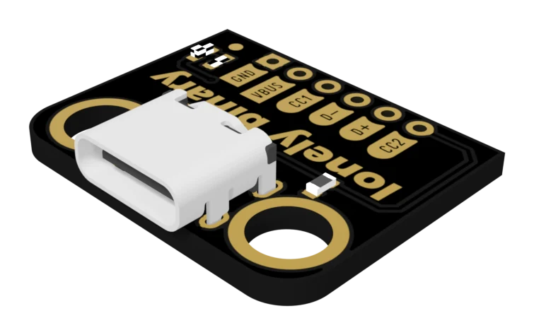
A USB-C socket, the two resistors already fitted, and every useful contact brought out to a row of holes on a 0.1 inch grid. Plug a charger into it and 5 V appears on VBUS, because the handshake has already been done for you at the factory.
That is the entire trick, and it is worth being clear about how small it is — there is no chip on this board, nothing to configure, and nothing that can go out of date. What it gives you is the one thing a bare connector cannot: a socket that a modern charger will actually talk to.
What it does not do
The handshake this board performs is the simplest one in the specification. It says a device is here and nothing more. It does not ask for 9 V or 20 V, it does not negotiate anything, and it has no way of telling you what the charger replied.
For that you want a PD trigger, which has a chip on it doing a real conversation. This board is the honest 5 V case — and 5 V is what most projects on a breadboard want anyway.
When it does not work
That is the normal behaviour of every USB-C source, not a fault in the socket. A charger keeps VBUS switched off until it sees 5.1 kΩ from a CC pin to ground. Add that resistor — to both CC pins, so it works either way up — and the same socket starts supplying. This board is that circuit, already built.
A USB-A port has no CC line and no handshake — it puts 5 V on the wire the moment anything is plugged in, which is why the A-to-C cable seems to prove your socket is fine. The C-to-C cable goes to a source that does check, and that is the one telling you the resistors are missing.
Some laptop ports and most power banks fall back to supplying 5 V regardless. Well-behaved chargers do not. Building on the behaviour of the lenient one means your project stops working the day somebody uses a different supply, so treat the strict charger as the correct one.
Twelve boards, four strips of header, and what the numbers on the bag actually add up to.
What is in the box →Edit this page — content/books/usb-c-breakout/a-socket-is-not-a-supply.mdx
Questions about this product
See what other owners have asked, and read their solutions.
USB-C Breakout Board, 12-Pack with 5.1 kΩ CC Resistors
Loading discussions…
Discuss this article
Ask about this page. The answer stays here, on the page it belongs to, for whoever hits the same wall next.