What is in the box
Twelve boards and four forty-pin strips, two straight and two right-angle. That is more than twice the header you need, which is the difference between choosing a strip and rationing one.
What the bag holds
- 12 breakout boards, each 19.0 × 24.0 mm, with the socket and both CC resistors already fitted.
- 2 × 40-pin straight breakaway male header strips.
- 2 × 40-pin right-angle breakaway male header strips.
The boards are finished in ENIG — immersion gold — so the pads are gold coloured rather than the dull silver of a cheaper finish. That matters more here than on most boards, because a breakout spends its life being soldered, unsoldered and handled.
The header arithmetic
Each board takes six pins. Twelve boards is seventy-two. The bag holds a hundred and sixty.
So there is no rationing to do. You can fit right-angle strips to the boards that will live on a breadboard and straight strips to the ones going into a socket, and still have most of two strips left over for something else.
The boards are identical
There is one design in the bag, twelve times. No variants, nothing to sort, and nothing printed on one board that is not printed on the other eleven. Both faces carry the same six pin names, so you can read the labels from whichever side you happen to be soldering from.
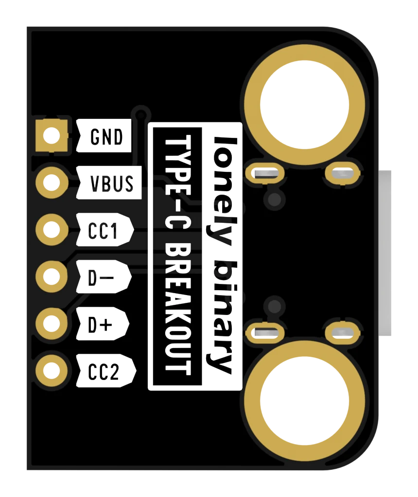
The two mounting holes are 4.8 mm across and 16.0 mm apart, plated right through so the ring cannot lift. That is a loose clearance hole for an M4 screw, or an M3 with a washer under the head. On a board that gets a cable pushed into it, bolting it down is worth the two minutes.
When it does not work
They are not meant to be. The strips arrive loose so you can pick straight or right-angle per board, and so a board can be soldered straight into a project with no header at all. Breaking six pins off a forty-pin strip takes a pair of pliers and about two seconds.
The right-angle strips have their pins bent through ninety degrees near one end, so the strip does not lie flat. The straight ones are a plain row of pins with the long side and the short side meeting the plastic spacer. Two of each are supplied.
Cosmetic marks on the black finish are normal on a panelised board that has been depanelled and bagged in twelves. What matters is that the gold pads are clean and the socket's shell is not bent. Check the socket's mouth is square before soldering a board in.
GND, VBUS, CC1, D−, D+, CC2 — an order nobody guesses, and the square pad that tells you where to start counting.
Six pins, in order →Edit this page — content/books/usb-c-breakout/whats-in-the-box.mdx
Questions about this product
See what other owners have asked, and read their solutions.
USB-C Breakout Board, 12-Pack with 5.1 kΩ CC Resistors
Loading discussions…
Discuss this article
Ask about this page. The answer stays here, on the page it belongs to, for whoever hits the same wall next.