Specifications
| In the box | 12 breakout boards, plus 2 × 40-pin straight and 2 × 40-pin right-angle breakaway male header strips. 160 header pins in total, against the 72 that twelve boards need |
|---|---|
| Pins | 6 pads on a 2.54 mm grid: GND, VBUS, CC1, D−, D+, CC2, top to bottom. The square pad is GND. Both faces carry the same labels |
| CC resistors | 5.1 kΩ from CC1 to GND and 5.1 kΩ from CC2 to GND, already fitted. Both are needed because a cable connects only one CC line, chosen by which way up the plug went in |
| Connector | SHOU HAN TYPE-C 16PIN 2MD(073), rated DC 5 V 3 A, −25 to +85 °C. 10000 insertion cycles, initial contact resistance 40 mΩ or less |
| What it negotiates | Nothing. The pull-downs say only that a device is present, so a source supplies 5 V and no more. Higher voltages need a Power Delivery chip, which this board does not have |
| Data | USB 2.0 only. D+ and D− are brought out; the socket bridges its two halves so the pair works either way up. No SuperSpeed pairs and no SBU pins |
| Power LED | Red, in series with 5.1 kΩ across VBUS — about 0.6 mA at 5 V. It proves the handshake worked, not that the source can supply your load |
| Direction | Sink only. It takes power from a charger. It cannot be the socket a phone plugs into, which needs pull-ups to 5 V instead |
| Board | 19.0 × 24.0 mm, ENIG gold finish. Two plated mounting holes 4.8 mm across and 16.0 mm apart |
What it does
A USB-C charger will not supply anything until it has been told there is a device on the other end of the cable. The only way to tell it is to pull a configuration channel pin — CC — down to ground through 5.1 kΩ.
This board is a USB-C socket with both of those resistors already fitted, and every useful contact brought out to a row of six holes on a 0.1 inch grid. Plug a charger in and 5 V appears on VBUS.
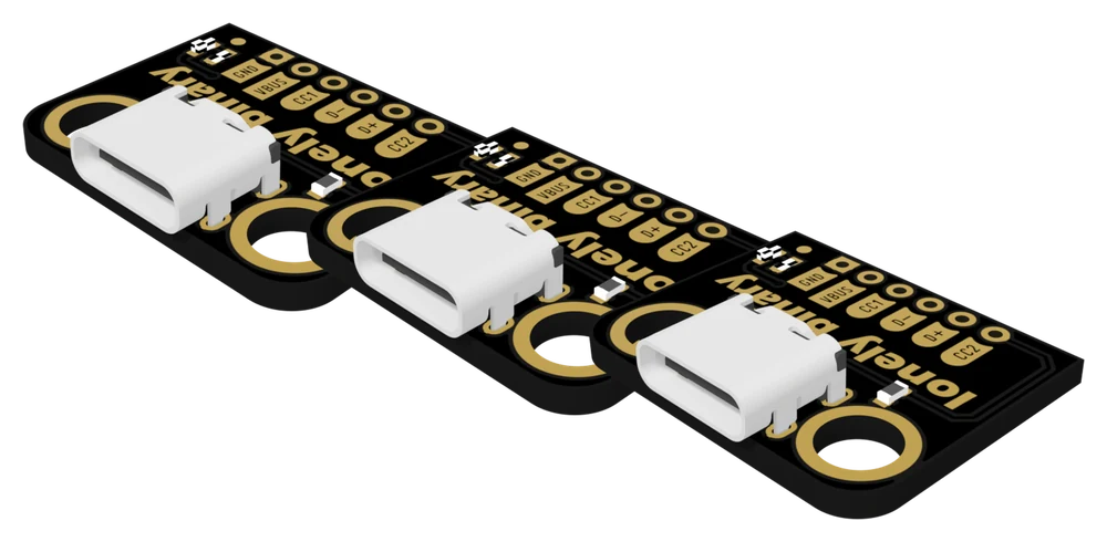
The six pads
Counting from the square pad, which is nearest the top edge with the socket on your left:
| Pad | What it is |
|---|---|
| GND | Ground. Square pad. Wire it first. |
| VBUS | 5 V from the source, once the handshake has happened. |
| CC1 | Configuration channel, already pulled to GND through 5.1 kΩ. |
| D− | The negative half of the USB 2.0 data pair. |
| D+ | The positive half. |
| CC2 | The other configuration channel, with its own 5.1 kΩ. |
It is not the order anybody guesses — a CC pin sits between the power and the data pair, and the second CC is on the far side of the data pins. Read the labels rather than counting from a photograph. They are printed on both faces.
Wiring, in four lines
- GND to your ground rail.
- VBUS to your 5 V rail, or to a board's 5V or VIN pin — never to 3V3.
- CC1 and CC2 to nothing. They are already finished.
- D− and D+ only if you want data, kept together and kept short.
Which board for which job
| You want | This board |
|---|---|
| 5 V out of a modern charger | Yes. This is the job it is built for. |
| USB 2.0 data as well as power | Yes, with D+ and D− wired. |
| To read what the source is offering | Yes — the CC pads are brought out so you can measure them. |
| 9 V, 12 V or 20 V from a charger | No. That needs a Power Delivery trigger. |
| A socket your phone plugs into to charge | No. That needs CC pull-ups, not pull-downs. |
| USB 3 SuperSpeed | No. Those pins are not brought out. |
Where to start
The handbook below is eleven short articles. If you only read two, read A socket is not a supply for why the resistors are the product, and It cannot be a host port for the one thing the board will never do — which is the mistake that costs people an evening, because it fails with no error message at all.
When it doesn’t work
- I soldered my own USB-C socket and VBUS reads 0 V. Is this board different?
- Yes, and this is the whole reason it exists. A USB-C source keeps VBUS switched off until it sees a device pull a CC line down through 5.1 kΩ. A bare socket has no such resistor, so the charger looks, finds an open circuit, and supplies nothing. This board has both resistors fitted, so the same charger switches on.
- Why are there two CC resistors instead of one?
- Because a USB-C cable carries a single CC wire, and which of the socket's two CC pins it lands on depends on which way up the plug went in. With a resistor on only one, the board would work half the time with no pattern the user can see. With both, one does the handshake and the other waits its turn.
- How much current can I draw?
- The socket is rated at 3 A, and 3 A is also the most a 5 V USB-C source ever offers. But nothing on this board reads what the source is advertising, so without measuring, the figure you are entitled to is 500 mA — that is what every source offers by default. What usually limits you first is not the socket at all: a 2.54 mm header pin, a breadboard contact and a thin jumper wire are all working hard above an amp.
- Can I use it to build a USB-C outlet for my phone?
- No, and this is the commonest disappointment with the part. A socket that hands power out has to pull CC up towards 5 V — 56 kΩ, 22 kΩ or 10 kΩ depending on what it is offering. This board pulls CC down. Two pull-downs facing each other means neither end detects anything, so no power flows and no fault is reported. You need a board built as a source.
- Does it do Power Delivery, or 9 V and 12 V?
- No. Two resistors can say a device is present and nothing else. Power Delivery is a protocol with messages in it, which needs a chip. This board gives you the 5 V case, which is what most breadboard projects want.
- Can I get USB 3 speeds through it?
- No. Only the USB 2.0 pair is brought out. The SuperSpeed pairs are not, because the board bridges the connector's two halves to make the plug reversible and that bridging would destroy a SuperSpeed signal. A USB 3 device plugged in will fall back to USB 2.0, which is what it is designed to do.
- Do the headers come soldered on?
- No. Four breakaway strips come loose in the bag — two straight and two right-angle — so you can choose per board. On a breadboard the right-angle strips are usually the better choice: the board lies flat and the push of a plug goes into the breadboard rather than levering on six solder joints.
- The power LED is much dimmer than on my other modules.
- It is meant to be. Its series resistor is 5.1 kΩ, the same value as the CC resistors, so it draws about 0.6 mA where an ordinary indicator takes fifteen or twenty. On a board whose job is handing the source's current to your circuit, an indicator eating 20 mA would be four per cent of a 500 mA budget spent on a light nobody looks at.