This lesson uses: Arduino UNO R3 board, TinkerBlock TK08 Rotary Potentiometer module, TinkerBlock TK01 XL LED module (optional), TinkerBlock TK07 Disc Potentiometer module (optional), jumper wires (or breadboard). Learn analog input and variables; use analogRead() to read the potentiometer and achieve outcome: when you turn the knob the serial monitor shows 0–1023, and the LED on D9 changes brightness (optional).
1. Wiring
TK08 Rotary Potentiometer (wire this first):
- GND → Arduino GND
- VCC → Arduino 5V
- SIGNAL → Arduino A0 (note: A0, not D0)
- NC leave unconnected
TK01 XL LED (optional, for observing potentiometer-controlled brightness):
- GND → Arduino GND
- SIGNAL → Arduino D9 (PWM pin; use 9 in code)
- NC leave unconnected
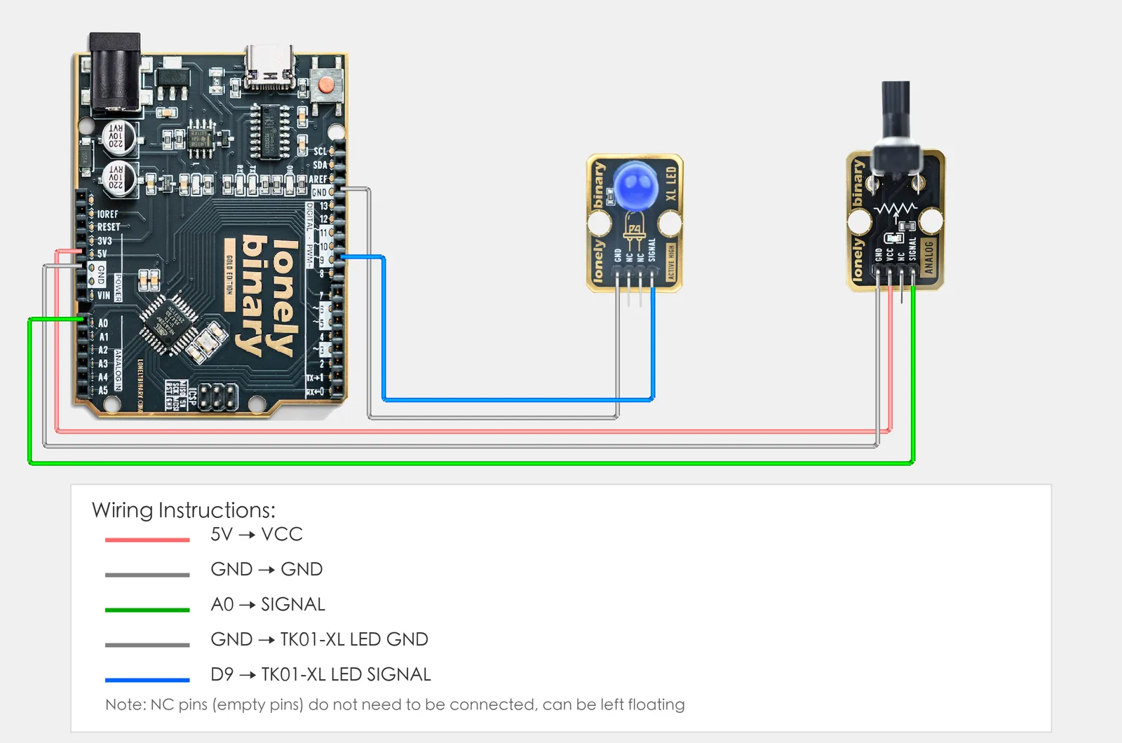
(Optional) If your kit has TK07 Disc Potentiometer, wire the same way: GND→GND, VCC→5V, SIGNAL→A1, NC unconnected.
2. New sketch
- Arduino IDE: File → New (or Ctrl/Cmd + N) to create a blank sketch
- Confirm board and port are selected (same as Lesson 01)
- Type the code below into the default
setup()andloop()yourself
3. Program structure
Same as last lesson: two fixed blocks setup() and loop().
setup(): Start the serial port (to see values on the computer); runs once.loop(): Keep repeating “read A0 → store in variable → use it to control D9 LED brightness (optional) → print value to serial → short delay”.
After uploading, turn the knob and the serial numbers will change; if the LED is connected, its brightness will change too.
4. Code to write
Type the code below line by line into setup() and loop() (do not copy-paste; typing it yourself helps you remember):
#define POT_PIN A0   // Potentiometer on A0
#define LED_PIN 9    // XL LED on D9 (PWM pin)

void setup() {
  pinMode(LED_PIN, OUTPUT);   // D9 output for LED (optional)
  Serial.begin(9600);         // Serial baud 9600 for printing potentiometer value
  Serial.println("Potentiometer program started");
}

void loop() {
  int val = analogRead(POT_PIN);   // Read A0, store in val (0-1023)

  // Use potentiometer value to control D9 LED brightness (map 0-1023 to 0-255)
  int brightness = val * 255L / 1023;
  analogWrite(LED_PIN, brightness);

  Serial.print("Potentiometer: ");
  Serial.println(val);   // Print to serial for observing knob change

  delay(200);   // Lower refresh rate for easier observation
}
Program notes
Overall idea: Read A0 for 0–1023, store in variable val; map with val * 255L / 1023 to 0–255 and use analogWrite to control D9 brightness; also print val to serial. Analog input and PWM output are both “multi-level”, so you get continuous dimming.
| Code | In this lesson |
|---|---|
#define POT_PIN A0 | Potentiometer SIGNAL on A0 (analog pin), not digital D0 |
int val | Integer variable holding analogRead result (0–1023) |
analogRead(POT_PIN) | Read A0 analog value; 0=min, 1023=max |
val * 255L / 1023 | Linear map 0–1023 to 0–255; 255L long avoids overflow |
analogWrite(LED_PIN, brightness) | PWM output; 0=off, 255=full; remove this and the line above if LED not connected |
Serial.println(val) | Print value to serial for observing potentiometer change |
5. Hands-on
- After entering the code, click Verify (✓) to compile
- Click Upload (→) to upload to the board
- Open Serial Monitor:
- Arduino IDE: Tools → Serial Monitor (or Ctrl/Cmd + Shift + M)
- Set baud rate to 9600 (bottom right)
- Watch the Serial Monitor:
- Rotate the TK08 potentiometer: values should change between 0–1023
- Knob fully left: value near 0
- Knob fully right: value near 1023
- If TK01 XL LED is on D9: LED brightness will follow the potentiometer (brighter as you turn right).
- (Optional) If TK07 disc potentiometer is connected, read A1 and observe both potentiometer values
Expected result: As in the figure. Serial values change when you turn the potentiometer; LED on D9 brightness changes accordingly.
Proceed to Lesson 12.
6. Common issues
| Symptom | What to do |
|---|---|
| Serial monitor shows nothing | Ensure Serial.begin(9600) is in setup(); set Serial Monitor baud to 9600 |
| Value always 0 or 1023 | Check TK08 wiring GND→GND, VCC→5V, SIGNAL→A0 (not D0); ensure knob can rotate |
| Value does not change | Ensure SIGNAL is on A0 (analog input), not D0 (digital input) |
Edit this page — content/guides/tinkerblock-workshop/11-potentiometers.mdx
Questions about this product
See what other owners have asked, and read their solutions.
This page covers several products. Choose yours to see the right discussions.
Discuss this article
Ask about this page. The answer stays here, on the page it belongs to, for whoever hits the same wall next.