Specifications
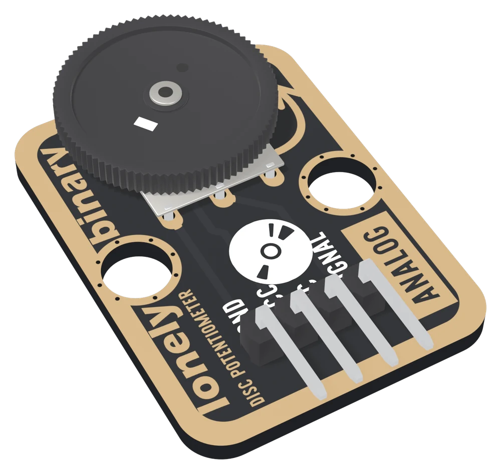
| Potentiometer | 10 kΩ single-gang thumbwheel, 16 mm across and 2.0 mm thick. Lies flat, face up, and overhangs the board's top edge by about 3.9 mm |
|---|---|
| Output | Analog voltage on SIGNAL from the wiper: 0 V at one stop to VCC at the other, SIGNAL = VCC × wheel position |
| Supply | 3.3 V or 5 V on VCC, which is the top of the range: 3V3 beside an ESP32, ESP32-S3 or Pico, 5V beside an Uno. The track draws 0.33 mA from 3.3 V, 0.5 mA from 5 V |
| Pins to wire | 3 of the 4: GND, VCC and SIGNAL. NC is connected to nothing on the board |
| Reading | 0 to 1023 on an Uno (10-bit), 0 to 4095 on an ESP32 or ESP32-S3 (12-bit), 0 to 1023 on a Pico in Arduino by default |
| Header | 4-pin right-angle male, 2.54 mm pitch: GND, VCC, NC, SIGNAL, with GND on the square pad |
| Board | 22.4 × 30.4 mm, two 4.8 mm mounting holes 16 mm apart |
| In the box | 1 × TK07 block. It also ships inside the TinkerBlock kits |
What it is
A thumbwheel potentiometer and nothing else. The ends of its 10 kΩ track go to GND and VCC, and the wiper, the contact that turns with the wheel, goes to SIGNAL. Turn the wheel and SIGNAL moves from 0 V at one stop to VCC at the other. One analog pin reads it as a number.
The number depends on the board, and this trips people moving between them. An Uno's ADC is 10-bit, so full scale is 1023. An ESP32's is 12-bit, so it is 4095. A sketch with 1023 written into it thinks it has reached the top a quarter of the way round on an ESP32 and looks like a broken pot.
The wheel lies flat instead of standing on a shaft. That is the reason to pick it over the TK08: nothing sticks up, and a lid can close over it with the edge of the wheel left showing.
VCC is the top of the range
At one stop the wiper sits on VCC, so the voltage on VCC is the most your analog pin will ever see:
| Your board | VCC to | SIGNAL runs | Reads |
|---|---|---|---|
| Arduino Uno | 5V | 0 to 5 V | 0 to 1023 |
| ESP32, ESP32-S3 | 3V3 | 0 to 3.3 V | 0 to 4095, flat for a few percent at each end |
| Raspberry Pi Pico | 3V3 | 0 to 3.3 V | 0 to 1023 in Arduino, 0 to 65535 with read_u16() |
Never 5V beside a 3.3 V board. With VCC unconnected every reading is 0.
Which pin is which
Wheel side up, header at the bottom, reading left to right:
| GND | to your board's GND | the square pad: count from here |
| VCC | to 3V3 or 5V | your board's logic voltage |
| NC | nothing | not connected on the board |
| SIGNAL | to an analog input | 0 V to VCC |
The back prints TK07 DISC POTENTIOMETER and TURN TO ADJUST RESISTANCE, OUTPUT AN ANALOG VOLTAGE SIGNAL instead of pin names. Turned over, the square pad is on the right, and it is still GND.
Wiring, in three lines
- GND to your board's GND.
- VCC to 5V on an Uno, 3V3 on an ESP32, ESP32-S3 or Pico.
- SIGNAL to an analog pin: A0 on an Uno, GPIO 34 on an ESP32, GPIO 4 on an ESP32-S3, GP26 on a Pico. On the ESP32s those are ADC1 pins, which keep working with Wi-Fi on.
Leave NC unconnected.
Example
// The pin SIGNAL is wired to.
// Uno: A0. ESP32: 34. ESP32-S3: 4. Pico: 26.
const int POT_PIN = 4;

// What analogRead returns at full scale on your board.
// Uno: 1023. ESP32, ESP32-S3: 4095. Pico: 1023.
const int ADC_MAX = 4095;

void setup() {
  Serial.begin(115200);
}

void loop() {
  int reading = analogRead(POT_PIN);
  int percent = map(reading, 0, ADC_MAX, 0, 100);

  Serial.print(reading);
  Serial.print("   ");
  Serial.print(percent);
  Serial.println(" %");
  delay(200);
}from machine import ADC, Pin
import sys
import time
# The GPIO number SIGNAL is wired to. ESP32: 34. ESP32-S3: 4. Pico: 26.
pot = ADC(Pin(4))
if sys.platform == "esp32": # both ESP32s
pot.atten(ADC.ATTN_11DB) # measure up to about 3.1 V
while True:
reading = pot.read_u16() # 0 .. 65535 on every board
print(reading, reading * 100 // 65535, "%")
time.sleep_ms(200)Where to start
The handbook below is nine short articles, each with a working figure. The first read is the whole build in three wires and a few lines.
Before plugging it into an ESP32, VCC sets the top is the page that protects the board. If the number wanders, read smoothing a jittery reading; if the stops are not 0 and full scale, why the ends are not exact.
When it doesn’t work
- Should VCC go to 3V3 or 5V?
- To your board's logic voltage: 3V3 on an ESP32, ESP32-S3 or Pico, 5V on an Uno. At one stop the wiper sits on VCC, so the voltage on VCC is the most your analog pin will see. 5V beside a 3.3 V board puts the pin past its rating for the last third of the wheel's travel.
- Full scale reads 1023 on one board and 4095 on another.
- 10-bit versus 12-bit ADC. The Uno's is 10-bit; the ESP32's and ESP32-S3's are 12-bit. The Pico's is 12-bit but arduino-pico reads it as 10-bit unless you call analogReadResolution(12). Keep the full-scale value in one constant and divide by it.
- The ESP32 reads 0 for the first bit of travel and 4095 for the last bit.
- That is the ESP32's ADC, not the block. With the Arduino core's default settings it reads from roughly 0.1 V to roughly 3.1 V, and the block gives it 0 to 3.3 V. Take your own two stops and map from them.
- The value jitters with the wheel held still.
- Normal, and more on an ESP32 than on an Uno. Average 16 reads per value; the handbook's smoothing sketch does it in six lines.
- Which way do I turn it to raise the reading?
- The part does not say, so turn it and watch. To reverse it, use the full-scale value minus the reading.
- Is the track linear or logarithmic?
- The part's drawing does not state the taper. The handbook's figures draw it linear; the first sketch shows you which yours is.